Outdated Drivers Are Slowing You Down
One free scan finds every outdated or missing driver and matches the right update for your exact hardware.Free scan · exact hardware matchPC Slower Than It Used to Be?
A free scan shows the junk files, broken settings and background clutter dragging Windows down - then fixes them in one click.Free scan · Windows 10 & 11Some links on this page are affiliate links: if you buy through them we may earn a commission, at no extra cost to you.
PCIe latency is the accumulated delay between a request being issued and useful work being completed, and it can come from far more than the link itself. Device controller behavior, switch hops, DMA setup, memory ordering rules, interrupt delivery, cache coherency, firmware policy, and driver scheduling all contribute to the time seen by applications and real-time workloads.
As PCIe systems scale across GPUs, NVMe drives, NICs, FPGAs, accelerators, and multi-root or switched topologies, small delays can compound into missed deadlines, reduced IOPS, lower packet throughput, or underutilized compute engines. End-to-end performance depends on how efficiently transactions move through the full path: endpoint, root complex, memory subsystem, operating system, and application.
As an Amazon Associate I earn from qualifying purchases.
Free tools Windows power users keep installed
One-click scans. No signup required.
Reducing latency requires a practical view of the complete stack: measuring transaction timing accurately, identifying bottlenecks across hardware and software boundaries, and tuning DMA, interrupts, queue depths, payload sizes, and traffic priorities. Modern designs benefit most when latency is treated as a system property rather than a single PCIe link metric.
How PCIe Latency Impacts System Performance
PCIe latency is the time consumed between a request being issued and the corresponding completion or visible effect reaching the requester. In practical systems, this delay includes packet formation in the endpoint, traversal through the root complex and any switches, arbitration on shared links, protocol overhead, memory controller response time, DMA engine scheduling, interrupt delivery, and software handling. A single PCIe transaction may complete in nanoseconds to low microseconds, but end-to-end application impact depends on how often those transactions occur and whether the workload can hide the delay with batching or parallelism.
Popular on Amazon

- 【7 ports PCIe USB card】 There is a 2-phase independent power supply module, which can feed one interface per output port to escape power shortage. Can operate without an external or auxiliary power supply; the seven interfaces operate independently and do not affect each other. Seven USB 3.0 Type A ports can be added externally to the PC case. Note: Not compatible with PS3/PS4.
- 【High Speed Transmission】USB3.0 theoretical speed up to 5Gbps, provides 10 times faster transmission speed than USB2.0. This usb expansion card enables quick access to files and transfer of HD movies, photos, music, etc.
- 【Stable power supply】The usb pcie card adopt NEC720201&NEC720210 chip. The USB interface can supply 5V2A power to external devices. Solid capacitors with good performance are used for low impedance, low temperature stability, and high temperature wave resistance.
- 【7 independent solid capacitors】Each interface has a stable voltage solid capacitor to ensure a stable power supply. The dielectric material of the solid capacitors is made of conductive polymer material, which has the advantages of high stability, long life, and low ESR (faster charging and discharging speed).
- 【Wide compatibility】 PCI-E X1 X4 X8 X16 compatible. Note: Not compatible with older PCI, backward compatible with USB 2.0 / 1.1, 64-bit and 32-bit Windows 11 / 10 / 8 / 7 / XP / Linux, not Mac compatible. Note: WIN8 and WIN10/11 users do not need to install the drive; XP and WIN7 users can download, unzip, install, and complete. (The corresponding installation directory for CD is DRIVERSǐ201R30230.EXE.)
The effect is most visible in workloads with small, frequent transfers. A storage controller reading large sequential blocks can amortize PCIe overhead across many kilobytes or megabytes, so bandwidth dominates. By contrast, a low-queue-depth NVMe read, a GPU command submission, an FPGA register access, or a network packet descriptor update may wait on mulle short PCIe transactions. In these cases, each microsecond added by a switch hop, completion timeout behavior, interrupt moderation setting, or driver lock can directly increase tail latency and reduce transactions per second.
Where latency shows up in the data path
- Endpoint access: Memory-mapped I/O reads are especially sensitive because the CPU often stalls until the completion returns. Posted writes can appear faster, but ordering rules and flush reads can expose accumulated delay.
- Switch traversal: Each PCIe switch adds packet buffering, routing lookup, arbitration, and possible congestion. Under load, head-of-line blocking can make latency less predictable even when average bandwidth remains acceptable.
- DMA movement: DMA reduces CPU involvement, but setup cost, descriptor fetches, address translation, IOMMU walks, cache coherency actions, and completion signaling all add delay before data becomes usable.
- Interrupt and completion handling: MSI-X delivery, interrupt remapping, CPU wakeup, scheduler activity, and driver callbacks can add more latency than the PCIe fabric itself, particularly on general-purpose operating systems.
Latency also affects aggregate throughput when the system cannot keep enough work in flight. PCIe links achieve high bandwidth through pipelining, outstanding requests, large payloads, and sufficient credits. If a device or driver waits for each completion before issuing the next request, link utilization collapses. For example, a DMA engine using a shallow descriptor queue may spend more time waiting for host memory completions than transferring payload data. Similarly, a NIC or accelerator placed behind an oversubscribed switch can experience completion delays that reduce effective packet rate or inference throughput.
End-to-end performance is often governed by the slowest interaction between hardware and software rather than by raw PCIe generation. Moving from PCIe Gen4 to Gen5 increases bandwidth and reduces serialization time, but it does not eliminate delays from non-uniform NUMA placement, interrupt routing to a remote CPU socket, inefficient driver polling, small transaction sizes, or congested peer-to-peer paths. A system with a lower-speed link but well-aligned CPU affinity, large DMA batches, and interrupt moderation may deliver better application latency than a faster link with poor topology and software placement.
Tail latency is especially critical in real-time, trading, storage, networking, and accelerator workloads. Average latency can look acceptable while the 99th or 99.9th percentile suffers from occasional switch congestion, power-state exits, ASPM transitions, firmware background tasks, or operating system scheduling delays. For this reason, PCIe latency must be evaluated as a complete path: device firmware, PCIe topology, host memory access, DMA queues, interrupt strategy, driver behavior, and application threading all contribute to the time observed by the workload.
Common Sources of Latency in PCIe Architectures
PCIe latency is rarely caused by a single component. It is the accumulated delay across the endpoint, root complex, switches, memory subsystem, DMA engine, interrupt path, and driver stack. A transaction that looks simple at the protocol level, such as a memory read from an accelerator or a descriptor fetch by a NIC, may cross several buffering, arbitration, translation, and completion stages before software observes the result. The most visible latency usually appears in small transactions, dependent reads, interrupt delivery, and control-plane operations where each microsecond directly affects completion time.
One major source is the PCIe transaction itself. Posted writes can move efficiently because the requester does not wait for a completion, but non-posted reads and configuration accesses require a request and a completion, making them sensitive to round-trip delay. Small memory reads are especially expensive because protocol overhead, packet assembly, flow-control credits, and completion latency dominate payload transfer time. Max Payload Size and Max Read Request Size settings also affect behavior: overly small values increase packet count, while poorly matched values can create inefficient completions or head-of-line blocking in shared paths.
Do these 3 things before closing this tab:
1Fix the driver behind crashes, sound loss and screen glitches2Clear out junk files and repair common Windows errors3Scan for outdated or missing drivers - takes under a minuteDevice, switch, and fabric delays
Endpoints add latency through internal queues, DMA schedulers, packetization , address translation units, and firmware-controlled command processors. A storage controller, GPU, FPGA, or NIC may accept a PCIe request quickly at the link layer but delay servicing it while internal resources are busy. PCIe switches add additional hop latency as packets are decoded, buffered, arbitrated, and forwarded between ports. In multi-switch topologies, uplink oversubscription and contention between peer devices can increase tail latency even when average bandwidth appears healthy.
Also popular on Amazon

- 1. This FS-U2S-Pro is a PCIE X1 interface to 2X 5Gbps (USB-A ports) USB 3.0 expansion card. Allow users add 2X 5Gbps max USB-A ports on Desktop PCs, MAC Pros, Working Stations, and NAS Data Centers for large data transfers. It will light up 2X USB 3.0 devices which including USB keyboard, USB mice, USB speakers, USB KVM switch, USB HUB, USB flash drive, printers, game pad, smartphone, tablet, and more USB-A interface devices.
- 2. Built in FebSmart Self-Powered Technology, users do not need to plug any additional power cable from PC’s power supply unit. Allow each 5Gbps USB-A port get 5V/2A (5V/4A in total) max power supply for high-power consuming USB 3.0 devices (NOT support fast charging) such as USB industrial cameras, USB VR-Systems, USB 3.0 NVME enclosures, USB SATA HDD/SSD enclosures, USB live broadcast devices, USB 3.0 video adapters and USB 3.0 universal docking stations.
- 3. Based on ASMedia ASM1042 5Gbps USB 3.0 host controller, will compatible with ARM, AMD, MAC, and Intel hardware platform Desktop PCs. FebSmart built in 2X voltage transformers to pick up 12V power from motherboard and covert to 5V/4A in total power supply for 2X USB 3.0 devices power consumption. Febsmart also designed 2X electronic safety fuse, 2X voltage stable capacitor and 2X voltage stable inductance to protect USB 3.0 devices and users’ data safety.
- 4. Compatible System: 1. Plug and Play on Windows 11, 10, 8.x (32/64bit) and Windows Server 2012, 2012R2, 2016, 2019, 2022 systems. 2. Need to Install Driver on Windows XP, Vista, 7 (32/64bit) and Windows Server 2003, 2003R2, 2008, 2008R2 (32/64bit) systems. 3. Plug and Play on most Linux kernels. 4. Plug and Play on most MAC OS.
- 5. PCIE X1 interface design, will works on PCIE X1, X2, X4, X8, X16 slot, do not work on PCI slot. Based on PCIE 2.0 standard, will compatible with PCIE 1.x, 2.x, 3.x, 4.x PCIE slot. The full height bracket mounted on this PCIE USB 3.0 expansion card, will works on Standard Size PCs. The low-profile bracket in the package, will supports Slim PCs.
- Link speed and width: A lower negotiated generation or fewer active lanes increases serialization time and can expose congestion sooner.
- Switch buffering: Deep buffers smooth bursts but may add queueing delay under sustained load.
- Credit starvation: Lack of posted, non-posted, or completion credits can stall transmission until the receiver returns credits.
- Retimers and redrivers: Signal-conditioning components can add small but measurable delay, especially across long risers or cable paths.
Memory, coherency, and address translation
Many PCIe paths eventually depend on host memory latency. DMA reads and writes traverse the root complex, memory controller, and sometimes an IOMMU before reaching DRAM. IOMMU address translation can add delay, particularly when translation lookaside buffers miss or when devices access many small, scattered buffers. In coherent systems, cache snoops and coherency ordering rules may further affect completion timing. NUMA placement is another frequent contributor: a device attached to one CPU socket but using memory allocated on another socket may incur inter-socket fabric latency for every DMA access.
Ordering rules can also limit concurrency. PCIe preserves ordering for certain traffic classes and transaction types, and drivers may unintentionally serialize work by using frequent readbacks, doorbell polling, or memory barriers. A common pattern is writing descriptors to host memory, ringing a device doorbell, and then polling status through MMIO reads. If each step forces ordering across the PCIe fabric and CPU memory hierarchy, the path becomes dominated by synchronization latency rather than link throughput.
Software and interrupt path latency
Software can add as much delay as hardware. Driver locks, kernel scheduling, interrupt moderation, power management, and buffer management all influence end-to-end response time. MSI or MSI-X interrupts still require routing through the platform interrupt controller and CPU cores, and the handler may wait behind other interrupt or kernel activity. Interrupt coalescing reduces CPU overhead but deliberately delays notification, so settings that are excellent for throughput can be poor for low-latency workloads.
Quick wins for a faster PC:
Fix the driver behind crashes, sound loss and screen glitchesFind Drivers →Clear out junk files and repair common Windows errorsFree Scan →Power states are another common source of unexpected delay. Active State Power Management, device low-power states, CPU package C-states, and clock gating reduce energy use but add wake-up time when traffic resumes. In latency-sensitive PCIe systems, the slowest operations are often first-packet events after idle periods, control register reads, page-mapped DMA accesses, or completions delayed by congestion. Identifying these sources separately is essential because each requires a different fix: topology changes for fabric delay, memory affinity for NUMA issues, larger DMA batches for descriptor overhead, or driver tuning for interrupt and scheduling latency.
Measuring and Profiling PCIe Transaction Latency
Accurate PCIe latency analysis starts by separating the path into measurable segments: application call, driver entry, DMA descriptor handling, PCIe transaction traversal, endpoint response, completion delivery, interrupt or polling detection, and user-space notification. A single “PCIe latency” number is rarely useful unless it states what is included. For example, a posted memory write from a host to an endpoint may appear fast because it does not wait for a completion, while a non-posted memory read exposes request propagation, endpoint service time, and completion return latency.
Use timestamping at mulle layers to avoid blaming the link for delays created elsewhere. In software, high-resolution CPU timers can bracket driver calls, MMIO accesses, DMA submission, and completion handling. In the kernel, tracing frameworks such as ftrace, perf, eBPF, ETW on Windows, or vendor driver tracepoints can show scheduling gaps, interrupt service time, deferred procedure work, and lock contention. In hardware, FPGA endpoints can latch cycle counters when TLPs arrive, descriptors are fetched, payloads are written, and completions are generated. Correlating these timestamps with host-side traces provides a practical end-to-end view.
Common measurement methods
- MMIO read latency tests: issue repeated uncached reads to endpoint registers and measure round-trip time. This captures non-posted transaction latency, including switch hops and endpoint response delay.
- Posted write visibility tests: write a doorbell register, then observe when the endpoint records the update. This requires endpoint-side timestamping because the host may retire the write before it reaches the device.
- DMA completion timing: timestamp descriptor submission, device fetch, data movement, write-back completion, and host observation. This exposes descriptor queue depth, read request size, payload size, and memory subsystem effects.
- Interrupt latency profiling: compare the device’s interrupt assertion time with the driver’s interrupt handler entry and application wake-up time. This helps distinguish PCIe delivery time from OS scheduling delay.
- Protocol analyzer captures: use a PCIe analyzer to inspect TLP ordering, completion gaps, replay events, flow-control stalls, malformed behavior, and link-state transitions.
When profiling, control the environment tightly. Pin test threads to specific CPU cores, disable deep CPU sleep states for latency-sensitive tests, use a fixed NUMA placement, and isolate the test from unrelated interrupts where possible. Verify negotiated link speed and width with tools such as lspci, platform firmware menus, or vendor utilities; an endpoint running at Gen3 x4 instead of Gen4 x8 can distort both latency and throughput results. Also inspect Max Payload Size, Max Read Request Size, relaxed ordering, no-snoop settings, ASPM state, and ACS routing, since these parameters can change transaction behavior across switches and root ports.
The Tool Desk
Outbyte PC Repair FREEClear out junk files and repair common Windows errorsFree Scan →Outbyte Driver Updater FREEScan for outdated or missing drivers - takes under a minuteDriver Scan →Also popular on Amazon
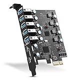
- Maximum extension,Most USB interfaces: Update your Computer to 7 ports USB3.0--2 Port Type C and 5 ports Type A, You can connect keyboard, mouse, external hard drives, CD/DVD drives, webcams,usb printers, scanners, game controllers,USB VR, digital cameras, etc
- Increasing Efficiency: Supports transfer rates of up to 5Gbps copying HD videos, music, photos,data files between USB devices and the computer at blazing fast speeds.Note:The actual transmission speed is limited by the setting of the device connected
- Widely compatibility: USB 3.0 Backwards compatible with USB 2.0 and 1.1 devices; Comply with PCI-e 3.0 PCIe 2.0 motherboards, Fits PCI Express x1, x4, x8 or x16 socket .Operating System Supports Windows XP/Vista/2008 Server/7/8/10,and Mac 0s (10.8.2 above) . Note: Windows XP,/Vista/7, Server,requires driver installation, Windows 10 and Mac OS 10.8.2 above don't need drivers
- Easy to install: Shut down the PC, unplug the power supply,remove the PC case,push the card in pcie socket and tighten the screws,and Close the PC case cover, turn on the PC and install the driver. quick and easy installation, a simple solution for connecting to and using USB 3.0 devices on your standard desktop PC. Packing list:1x PCIE USB expansion card, 1x CD driver, 2 x installation screws and 1x user manual
- Considerate Service: This card is the best choice for standard tower case and motherboard upgrade USB ports. We offer 2 years of-Product-Care for USB PCIE card. In addition, rest assured that we provide 24/7 support for our products and customers
| Symptom | Likely area to inspect | Useful evidence |
|---|---|---|
| High MMIO read time | Switch depth, endpoint register path, completion delay | Analyzer completion timestamps, endpoint register access counters |
| Fast DMA but slow application response | Interrupt moderation, driver queue handling, scheduler wake-up | Kernel trace, ISR timestamps, application receive timestamps |
| Latency spikes under load | Flow-control credits, memory contention, shared switch uplinks | TLP gaps, replay counters, bandwidth counters, NUMA metrics |
| Variable read completion time | MRRS tuning, endpoint completion batching, host memory pressure | Completion size distribution, queue occupancy, memory controller counters |
Repeat tests across idle, steady-state, and worst-case traffic patterns. Average latency hides tail behavior, so record percentiles such as p50, p95, p99, and maximum observed delay. For real-time data acquisition, trading, storage, or accelerator control paths, the p99 latency often determines whether the design is usable. A disciplined measurement setup that combines software tracing, endpoint instrumentation, and PCIe protocol visibility makes it possible to locate the dominant delay instead of tuning blindly.
Hardware Design Strategies for Lower Latency
Lower PCIe latency starts with topology. Each retimer, bridge, and switch hop adds serialization delay, buffering, arbitration, and clock-domain crossing overhead, so latency-sensitive devices should sit as close to the CPU root complex as the platform allows. For example, an FPGA used for packet inspection or a GPU used for real-time inference will usually see better round-trip behavior on a direct CPU-attached x16 slot than behind a downstream switch shared with storage and networking devices. When a switch is required, choose one with cut-through forwarding, adequate non-blocking bandwidth, and configurable virtual channels or traffic classes rather than relying only on peak lane count.
Lane width and link generation also matter, but not always in the obvious way. Moving from PCIe Gen4 to Gen5 reduces transfer time for large payloads, while small control transactions may still be dominated by completion latency, switch traversal, and device response time. A wider link can reduce queue buildup under load, which indirectly lowers tail latency, even if the baseline latency of a single memory read changes only modestly. Designers should validate negotiated link speed and width at boot and under thermal stress, because fallback from x16 to x8 or Gen5 to Gen4 can create intermittent performance shifts that look like software jitter.
Topology and placement choices
- Prefer direct root-complex attachment for latency-critical endpoints such as NICs, NVMe drives used for synchronous logging, accelerator cards, and timing devices.
- Avoid unnecessary switch cascades; two smaller switches in series can produce worse completion latency than one properly sized switch.
- Keep peer-to-peer paths short when devices exchange data without CPU memory staging, such as GPU-to-NIC or FPGA-to-NVMe designs.
- Separate bursty devices from low-latency devices where possible, especially when storage arrays, capture cards, and accelerators share the same downstream ports.
Endpoint design is just as influential as board topology. Devices that post writes efficiently, keep enough read requests outstanding, and return completions quickly will outperform devices that serialize internal work behind shallow queues. FPGA and ASIC endpoints should minimize internal buffering stages on the control path, avoid slow register access paths for frequently polled status, and use completion timeout settings that reflect the actual service model. For memory reads, increasing outstanding request capability and Max Read Request Size can improve throughput, but very large requests may increase head-of-line blocking for short control reads. A balanced design often uses larger requests for bulk DMA and smaller, prioritized paths for doorbells, descriptors, and status fetches.
What’s actually slowing this PC down?
Pick the symptom - the matching free tool is one click away.
Platform firmware settings can either preserve or undermine hardware latency goals. Active State Power Management, L1 substates, clock gating, and aggressive package C-states save power but add exit latency when traffic resumes. Systems built for deterministic response often disable the deepest PCIe link power states on critical links, lock expected link speeds, and ensure Above 4G decoding, Resizable BAR, and IOMMU mappings are configured consistently. Signal integrity also has a latency effect: marginal channels that trigger replay events, equalization retries, or link retraining create spikes far larger than normal packet transit time. Clean routing, validated retimer placement, controlled impedance, and thermal margin around high-speed components help keep the link out of recovery paths.
| Design area | Low-latency practice | Latency benefit |
|---|---|---|
| Topology | Place critical endpoints on direct CPU lanes | Reduces switch and arbitration delay |
| Switching | Use low-latency switches with sufficient downstream bandwidth | Limits congestion and tail latency |
| Endpoint architecture | Separate control paths from bulk DMA paths | Keeps doorbells and status reads responsive |
| Power management | Restrict deep link sleep states on critical links | Avoids wake-up penalties |
Firmware and Driver Optimizations
Firmware and drivers sit between PCIe hardware capability and application-visible latency. Even when the link, switch fabric, and endpoint design are sound, poor initialization choices or inefficient driver paths can add microseconds through conservative settings, excessive register polling, serialized queues, or avoidable kernel transitions. Low-latency PCIe tuning starts with verifying that firmware configures each device for the intended operating mode: negotiated link speed and width, Max Payload Size, Max Read Request Size, relaxed ordering policy, completion timeout values, interrupt mode, and power-management behavior.
System firmware should avoid leaving latency-sensitive devices in settings chosen for broad compatibility rather than performance. Active State Power Management can save energy, but L0s and L1 transitions may add wake latency that is unacceptable for trading systems, packet processing, storage targets, or real-time acquisition. Similarly, clock power management and deep platform C-states can increase response time after idle periods. For deterministic latency, BIOS or UEFI settings often need to disable aggressive PCIe power savings for selected slots while still allowing less critical devices to use them.
Also popular on Amazon

- Instantly add 7 high-speed USB 3.0 ports to your desktop PC via PCIe slot, solving the problem of insufficient USB ports for peripherals like keyboards, mice, printers, and external drives.
- Delivers blazing-fast data transfer speeds up to 5Gbps (10x faster than USB 2.0), ideal for transferring large files, HD videos, or gaming peripherals without lag.
- Features UASP (USB Attached SCSI Protocol) technology and 4 dedicated channels to maximize throughput and reduce CPU load by up to 20%, ensuring smoother multitasking.
- Plug-and-play installation with driver-free support for Windows 11/10/8/7/XP/Vista and Linux (Note: Some older systems may require drivers). Compatible with gaming PCs, workstations, and servers.
- Equipped with over-current protection and a heat-dissipating aluminum heatsink to prevent overheating, ensuring stable performance even during prolonged heavy use
Driver paths that commonly add delay
- Excessive MMIO reads: posted writes are fast, but MMIO reads require completions and can stall the CPU until data returns. Drivers should cache state where safe and batch status reads.
- Unnecessary register polling: tight polling loops can waste CPU cycles, while slow polling intervals add latency. Hybrid approaches using short bounded polling followed by interrupts often work better.
- Global locks: a single driver lock around submission and completion handling can serialize work across queues, cores, or functions.
- Frequent DMA mapping operations: mapping and unmapping small buffers for every request can dominate latency. Pre-mapped rings, buffer pools, and IOMMU-aware allocation reduce this cost.
- Interrupt moderation set too high: coalescing improves throughput but can delay completions. Latency-sensitive queues should use separate moderation profiles from bulk-transfer queues.
Initialization code should also program queue layout with CPU locality in mind. MSI-X vectors, completion queues, and submission queues should be assigned to the NUMA node closest to the PCIe root complex. Driver interrupt affinity should place completion handling on cores that also run the application thread or its I/O worker. This avoids cross-socket cache transfers and reduces the time between device completion, interrupt delivery, driver processing, and user-space notification. On Linux, this usually involves checking NUMA placement, IRQ affinity, Receive Packet Steering or equivalent queue steering, and whether the process scheduler is moving latency-critical threads away from the device-local CPUs.
Recommended Free Tools
Firmware updates can also reduce latency by changing endpoint behavior below the driver interface. Device firmware may improve queue arbitration, completion generation, doorbell handling, credit usage, or internal DMA scheduling. For NVMe drives, network adapters, FPGAs, GPUs, and accelerators, different firmware releases can change tail latency even when average throughput is unchanged. Validation should compare not only bandwidth but also percentile latency, such as p99 and p99.9 completion time, under the same queue depth and payload size.
Practical optimization checklist
- Confirm negotiated PCIe generation and lane width after boot and after warm reset.
- Review BIOS or UEFI PCIe power-management settings for the target slot.
- Use MSI-X with per-queue vectors instead of sharing a legacy interrupt line.
- Pin interrupts, driver worker threads, and application threads to device-local CPUs.
- Reduce MMIO reads in the hot path and prefer batched doorbell writes where supported.
- Use persistent DMA buffers or memory pools for small, repeated transfers.
- Tune interrupt moderation separately for low-latency and high-throughput workloads.
- Measure latency before and after firmware, BIOS, kernel, or driver changes.
The best results usually come from aligning firmware configuration, driver architecture, and workload behavior. A device intended for high-throughput batch transfers can tolerate deeper queues and heavier interrupt coalescing, while a latency-sensitive device benefits from shallow queues, fast completion signaling, CPU locality, and minimal MMIO round trips. Treating these settings as workload-specific controls rather than fixed defaults helps turn PCIe capability into predictable end-to-end performance.
Independent reader supportYour contribution helps us test, update, and keep practical guides available for everyone.Tuning DMA, Interrupts, and Traffic Flow
DMA configuration has a direct impact on PCIe latency because it controls how often an endpoint touches host memory, how large each transfer is, and how much work the driver must do to prepare descriptors. Very small DMA transactions reduce per-transfer waiting time but can waste bandwidth on packet overhead and descriptor processing. Very large transfers improve throughput but may increase queuing delay for latency-sensitive requests behind them. A practical design usually separates traffic classes: short control messages and completion-sensitive reads use compact rings and frequent doorbell updates, while bulk data moves through deeper queues with larger descriptors.
Descriptor ring sizing should match the workload rather than simply being made as large as possible. Deep rings can hide software scheduling delays, but they also allow the device to build long internal queues that add tail latency. For low-latency paths, use enough descriptors to avoid starvation under normal load, then apply backpressure before queues grow excessively. Align DMA buffers to cache-line and page boundaries where possible, avoid crossing unnecessary 4 KB boundaries, and use scatter-gather lists that are compact enough for the device to fetch efficiently. On systems with an IOMMU, map buffers in batches, reuse mappings when safe, and prefer huge pages for long-lived high-rate buffers to reduce translation pressure.
Interrupt and polling choices
Interrupt delivery can dominate end-to-end latency when each completion must travel through MSI-X delivery, interrupt remapping, CPU wake-up, scheduler paths, and driver handling. MSI-X should be used instead of shared legacy interrupts so each queue can target a specific CPU. Pin each interrupt vector to the CPU closest to the PCIe root complex or NUMA node that owns the DMA buffers. For very high event rates, interrupt moderation reduces CPU overhead but increases response time; tune moderation timers in microseconds, not arbitrary defaults. A common pattern is adaptive moderation: minimal delay for sparse traffic, higher coalescing only when completion rates rise.
Polling can reduce latency variance by removing interrupt delivery from the critical path, but it consumes CPU cycles. Hybrid schemes are often best: poll briefly after submitting work or after receiving an interrupt, then fall back to interrupts when idle. Storage, networking, and accelerator drivers commonly use per-queue polling loops for hot paths while reserving interrupts for low-rate control events. The goal is not to eliminate interrupts everywhere, but to keep them off the most latency-sensitive completion path.
Also popular on Amazon

- HIGH-PERFORMANCE USB CARD: Upgrade or expand a desktop/server's USB connectivity by adding four external USB Type-C 10Gbps ports and one internal USB Type-A 10Gbps port via a single PCI Express x4 connection
- FAST DATA TRANSFER: ASM3142 controller supports USB 3.2 transfer speeds of up to 10Gbps; Ideal for transferring large files or editing high-resolution photos/videos on external storage devices
- OPTIONAL POWER: USB PCIe expansion card with SATA power supplies additional power to the USB ports (when motherboard power is insufficient), providing up to 5V 3A (15W) per USB Type-C port and 5V 1.5A (7.5W) on the USB Type-A port
- COMPATIBILITY: Drivers auto-install in most OS's including Windows 8 & up, macOS, and Linux; Works with all hardware platforms such as Intel, AMD, and Apple Silicon that have a PCI Express x4/x8/x16 slot; Does not support DP-Alt Mode/USB Power Delivery
- THE IT PRO'S CHOICE: Designed and built for IT Professionals, this 5-port USB-C PCIe Card is backed for 2-years, including free lifetime 24/5 multi-lingual technical assistance
Traffic flow controls that reduce waiting
- Separate queues by priority: isolate control, completion, and bulk-transfer traffic so large DMA operations do not block short requests.
- Use multiple MSI-X vectors: map each queue to its own interrupt vector and CPU affinity target to reduce lock contention and cache bouncing.
- Batch doorbells carefully: batching reduces MMIO writes, but excessive batching delays device visibility of new work.
- Limit outstanding reads: tune non-posted request depth so endpoints do not overload completion buffers or create head-of-line blocking.
- Match NUMA placement: allocate buffers, run driver threads, and route interrupts on the same socket as the PCIe root port whenever possible.
Validation should use both average latency and tail percentiles under realistic load. Measure queue residency time, DMA mapping cost, interrupt-to-handler time, completion processing time, and application wake-up time separately. PCIe analyzers, device counters, kernel tracing, and driver timestamps can then show whether delays come from the bus, the endpoint, the IOMMU, interrupt handling, or software scheduling. Effective tuning is iterative: reduce one queue, retest under contention, check tail latency, and confirm that throughput remains within the required envelope.
Frequently Asked Questions
What is a typical PCIe latency range for device-to-host transfers?
For a well-tuned system, a PCIe transaction can complete in hundreds of nanoseconds to a few microseconds, depending on topology, payload size, switch hops, chipset path, and whether data is already available at the endpoint. End-to-end latency is usually higher because it includes DMA setup, memory access, interrupt delivery, driver handling, and application wake-up time.
How much latency does a PCIe switch add?
A PCIe switch typically adds tens to hundreds of nanoseconds per hop, but the exact value depends on the switch architecture, link speed, port configuration, buffering, and traffic contention. Under load, queuing inside the switch can add much more latency than the base forwarding delay, especially when mulle endpoints compete for the same upstream link.
How can I measure PCIe latency accurately instead of guessing from throughput numbers?
Use hardware timestamping when available, endpoint counters, PCIe protocol analyzers, CPU timestamp counters, and driver-level tracing to separate device, bus, interrupt, and software delays. Measure small transfers, large transfers, idle conditions, and loaded conditions separately because average throughput can hide tail latency and queuing delays.
Does using DMA always reduce PCIe latency?
DMA reduces CPU involvement and improves efficiency for many workloads, but it does not always reduce latency for small or sporadic transfers. Descriptor setup, cache synchronization, IOMMU translation, batching, and interrupt moderation can add delay, so low-latency DMA paths often use pre-posted buffers, pinned memory, tuned queue depths, and carefully chosen completion policies.
What driver settings usually have the biggest impact on PCIe latency?
Interrupt moderation, queue depth, DMA buffer sizing, polling versus interrupt mode, NUMA placement, CPU affinity, and power management settings often have the largest effect. For latency-sensitive systems, keep the device, memory, and application thread on the same NUMA node, reduce excessive batching, disable deep power-saving states when appropriate, and test MSI-X affinity settings under realistic traffic.
Bottom Line
PCIe latency is the result of many small delays adding up across endpoints, switches, DMA engines, memory subsystems, interrupts, drivers, and application software. Reducing it starts with measuring the full path, separating hardware effects from software overhead, and identifying whether the real bottleneck is topology, transaction behavior, buffering, power management, or host-side processing.
For modern designs, the next step is to validate latency early with realistic traffic, tune BIOS and OS settings, optimize DMA and interrupt paths, and choose PCIe topology carefully. Treat latency as a system-level design target—not just a bus specification—and each device in the chain becomes easier to diagnose, benchmark, and improve.
Quick Recap
Product prices and availability are accurate as of the date/time indicated and are subject to change. Any price and availability information displayed on Amazon at the time of purchase will apply.

