Free tools Windows power users keep installed
One-click scans. No signup required.
Some links on this page are affiliate links: if you buy through them we may earn a commission, at no extra cost to you.
The nRF24L01+ is a low-cost 2.4GHz wireless transceiver that can let a Raspberry Pi exchange small packets of data with Arduino boards, other Pi devices, or embedded sensors. It communicates over SPI, so the connection is straightforward once the Raspberry Pi’s SPI interface is enabled and the module is wired to the correct GPIO pins.
Getting reliable communication depends heavily on proper wiring and stable 3.3V power. The nRF24L01+ is not 5V tolerant, and many connection problems come from weak power rails, missing decoupling capacitors, or mismatched CE and CSN pin settings in software.
As an Amazon Associate I earn from qualifying purchases.
The Tool Desk
Outbyte Driver Updater FREEScan for outdated or missing drivers - takes under a minuteDriver Scan →Outbyte PC Repair FREERepair Windows errors before they cause bigger problemsFix Now →This guide covers the parts you need, the correct pin mapping between the nRF24L01+ and Raspberry Pi, how to enable SPI, install common libraries, and run a simple test to confirm that the radio module is responding and ready for wireless communication.
Required Parts and Raspberry Pi SPI Basics
Before wiring the nRF24L01+ to a Raspberry Pi, gather the parts needed for a stable SPI connection. The nRF24L01+ is inexpensive and compact, but it is sensitive to poor power delivery and incorrect pin selection. A standard Raspberry Pi 40-pin header provides the SPI signals, 3.3 V power, and ground required by the module, so no USB adapter is needed for basic use.
Popular on Amazon

- HiLetgo 4pcs NRF24L01+ Wireless Transceiver Module
- Multi-frequency: 125 frequency points
- Low operating voltage : 1.9 ~ 3.6V low voltage operation
Parts you will need
- Raspberry Pi with a 40-pin GPIO header, such as a Raspberry Pi 3, 4, 5, Zero 2 W, or Zero W.
- nRF24L01+ 2.4 GHz transceiver module, either the small PCB antenna version or the PA/LNA version with an external antenna.
- Female-to-female jumper wires for connecting the module to the Raspberry Pi GPIO header.
- 10 µF to 100 µF capacitor placed across VCC and GND at the nRF24L01+ module to reduce voltage dips.
- Breadboard or GPIO breakout board, optional but useful for neat wiring and easier troubleshooting.
- Second nRF24L01+ device for testing communication, such as another Raspberry Pi, Arduino, ESP32, or microcontroller running compatible nRF24 software.
The nRF24L01+ runs at 3.3 V only. Its VCC pin must never be connected to the Raspberry Pi 5 V pin. Although the SPI signal pins on the Raspberry Pi are also 3.3 V and are safe to connect directly, the radio’s power input needs special attention. The small PCB antenna modules usually draw modest current, while PA/LNA modules with an external antenna can draw much more during transmission. If you use a high-power PA/LNA board, a separate regulated 3.3 V supply is often more reliable than powering it directly from the Pi’s 3.3 V rail.
Raspberry Pi SPI basics
SPI, or Serial Peripheral Interface, is a synchronous bus that uses separate lines for data going to and from the peripheral. On the Raspberry Pi, the primary SPI bus is commonly exposed as SPI0. It includes SCLK for the clock, MOSI for data from the Pi to the radio, and MISO for data from the radio back to the Pi. A chip-select line chooses which SPI device is active on the bus.
PC Slower Than It Used to Be?
A free scan shows the junk files, broken settings and background clutter dragging Windows down - then fixes them in one click.Free scan · Windows 10 & 11Crashes, No Sound, or Screen Glitches?
Random freezes, missing sound and display glitches usually trace back to one bad driver. Find and replace yours safely.Free scan · under a minute| SPI signal | Purpose | Typical Raspberry Pi GPIO |
|---|---|---|
| SCLK | Clock generated by the Raspberry Pi | GPIO11 |
| MOSI | Data from Raspberry Pi to nRF24L01+ | GPIO10 |
| MISO | Data from nRF24L01+ to Raspberry Pi | GPIO9 |
| CSN | SPI chip select for the nRF24L01+ | GPIO8, also called CE0 |
The nRF24L01+ also has a separate CE pin, which is not the same as the Raspberry Pi’s SPI chip-select pin. CE controls the radio’s transmit and receive modes, while CSN selects the module for SPI commands. Many connection problems come from mixing up these two pins in wiring or software. A common setup uses GPIO25 for CE and GPIO8 for CSN, but other GPIO pins can be used for CE if the software configuration matches the wiring.
nRF24L01+ Pinout and Raspberry Pi GPIO Mapping
The nRF24L01+ module uses an SPI interface, so it connects to the Raspberry Pi’s SPI clock, data, and chip-select pins, plus one extra GPIO for the module’s CE line. Most small nRF24L01+ breakout boards have an 8-pin header labeled GND, VCC, CE, CSN, SCK, MOSI, MISO, IRQ. The labels matter more than the physical order, because different breakout boards may arrange the pins differently.
The module must be powered from 3.3V only. Do not connect VCC to the Raspberry Pi’s 5V pin, as the nRF24L01+ is not 5V tolerant and can be permanently damaged. The SPI signal pins from the Raspberry Pi are already 3.3V, so no level shifter is needed when using a standard Pi GPIO header.
Recommended wiring table
| nRF24L01+ pin | Function | Raspberry Pi GPIO name | Physical pin |
|---|---|---|---|
| GND | Ground | GND | Pin 6, 9, 14, 20, 25, 30, 34, or 39 |
| VCC | 3.3V power | 3V3 | Pin 1 or 17 |
| CE | Chip enable | GPIO25 | Pin 22 |
| CSN | SPI chip select | GPIO8 / CE0 | Pin 24 |
| SCK | SPI clock | GPIO11 / SCLK | Pin 23 |
| MOSI | SPI data from Pi to module | GPIO10 / MOSI | Pin 19 |
| MISO | SPI data from module to Pi | GPIO9 / MISO | Pin 21 |
| IRQ | Interrupt output | Not connected for basic tests | Optional GPIO |
In this mapping, CSN uses the Raspberry Pi’s hardware SPI chip select CE0, which appears in Linux as SPI device /dev/spidev0.0. If you connect CSN to GPIO7 instead, you are using CE1, which appears as /dev/spidev0.1. The software configuration must match the physical CSN connection, otherwise the module may appear dead even though the wiring looks correct.
CE is separate from CSN. CE controls the nRF24L01+ radio state, such as transmit and receive mode, while CSN selects the module for SPI register access. Many examples use GPIO25 for CE, but GPIO22, GPIO24, or another free GPIO can also work if the library is configured with the same number. When following examples, check whether the library expects BCM GPIO numbering or physical header pin numbering. For example, CE on BCM GPIO25 is physical pin 22; confusing those two numbering systems is a common source of failed tests.
The IRQ pin is optional for a first setup. It can be connected to a free GPIO later if you want interrupt-driven receive handling, but most basic Python and C++ examples can poll the module status over SPI without using IRQ. For initial verification, leave IRQ disconnected and focus on stable 3.3V, shared ground, correct SPI pins, and matching CE/CSN settings in the test program.
Wiring the Module Safely
The nRF24L01+ is a 3.3V-only radio module, so wire it carefully before applying power. The Raspberry Pi’s GPIO header provides both 5V and 3.3V pins, but the radio must be connected only to 3.3V for VCC and to 3.3V SPI/GPIO signals. Do not connect the module’s VCC pin to a 5V pin; doing so can permanently damage the transceiver. The SPI signal pins on the Raspberry Pi are already 3.3V, so no level shifter is needed when connecting directly to the Pi.
With the Raspberry Pi powered off, place the nRF24L01+ module on a breadboard or use female-to-female jumper wires. Keep the wires short, especially for VCC, GND, SCK, MOSI, and MISO. Long, loose jumper wires can introduce noise and intermittent SPI failures. If you are using the common small nRF24L01+ board with an 8-pin header, double-check the pin labels printed on your exact module because some boards are oriented differently.
What’s actually slowing this PC down?
Pick the symptom - the matching free tool is one click away.
Also popular on Amazon
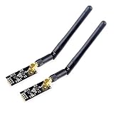
- High-performance wireless data transmission chip NRF24L01 +, an increase of high-power PA and LNA chips, RF switches, band-pass filters and other professional full bidirectional RF power amplifier, making the effective communication distance has been greatly expanded.
- NRF24L01P + PA + LNA wireless module works in the license-free 2.4G ISM band, can be point-to-point applications can also form a star network.
- In the RF part of a large number of optimized matching debugging, making the highest transmission efficiency, the smallest harmonic, making NRF24L01P + PA + LNA wireless module to external radio equipment to achieve the lowest radio frequency interference, but also not susceptible to interference from other devices, extremely large Improve the stability of the work.
- NRF24L01P + PA + LNA wireless module is highly integrated, the size of only 41mm * 15.5mm, easy to embed in any space-stressed products.
- Customers only need to add one MCU to control NRF24L01P + PA + LNA through SPI port ,Wireless module to complete ultra-long-range wireless data transmission system design.Do not need to worry about R & D of RF part, drastically reduce R & D expense and shorten R & D cycle.
| nRF24L01+ Pin | Raspberry Pi Pin | GPIO / Function |
|---|---|---|
| VCC | Pin 1 | 3.3V power |
| GND | Pin 6 | Ground |
| CE | Pin 22 | GPIO25 |
| CSN / CS | Pin 24 | GPIO8 / SPI CE0 |
| SCK | Pin 23 | GPIO11 / SPI SCLK |
| MOSI | Pin 19 | GPIO10 / SPI MOSI |
| MISO | Pin 21 | GPIO9 / SPI MISO |
| IRQ | Not connected | Optional interrupt pin |
Connect VCC to Raspberry Pi physical pin 1, which is 3.3V, and connect GND to any Pi ground pin such as physical pin 6. Then connect the SPI bus: SCK to pin 23, MOSI to pin 19, and MISO to pin 21. Use CSN on physical pin 24 if your software is configured for SPI device 0, commonly shown as /dev/spidev0.0. Connect CE to a regular GPIO pin such as GPIO25 on physical pin 22; CE is not the same as CSN and must be configured separately in your test program or library setup.
Power stability is often the difference between a working and non-working nRF24L01+ setup. Although the module runs at 3.3V, it can draw sharp current bursts while transmitting, especially the PA+LNA versions with an external antenna. The Raspberry Pi’s 3.3V rail may work with the small PCB antenna version, but many users still see failed initialization, random packet loss, or communication that works only at very short range. Place a capacitor close to the radio module between VCC and GND, typically 10 µF to 47 µF, with an additional 100 nF ceramic capacitor if available. Observe capacitor polarity for electrolytic capacitors.
For high-power nRF24L01+ PA+LNA modules, use a separate regulated 3.3V supply capable of providing enough current, often at least 250 mA. When using an external 3.3V regulator, connect the regulator’s ground to the Raspberry Pi ground so the SPI signals share the same reference. Do not power the radio from a 5V USB adapter without a 3.3V regulator. After wiring, inspect every connection against the pin labels, then power the Pi and proceed to software setup only after confirming that VCC is on 3.3V and ground is common.
Enabling SPI and Installing Libraries
After the nRF24L01+ is wired to the Raspberry Pi, the next step is to enable the Pi’s SPI interface and install the software needed to talk to the radio. The nRF24L01+ communicates over SPI, so the Raspberry Pi must expose its SPI device files, typically /dev/spidev0.0 and /dev/spidev0.1. These correspond to SPI bus 0 with chip select 0 and chip select 1. If you wired the module’s CSN pin to GPIO8, also called CE0, your code will usually use /dev/spidev0.0.
On Raspberry Pi OS with a desktop, open Preferences > Raspberry Pi Configuration, go to the Interfaces tab, enable SPI, and reboot if prompted. From the terminal, you can do the same with sudo raspi-config. Choose Interface Options, select SPI, enable it, then exit and reboot the Pi. After rebooting, confirm that SPI is active by listing the device files:
ls /dev/spidev*
You should see one or more SPI devices, such as /dev/spidev0.0 and /dev/spidev0.1. If nothing appears, check that SPI is enabled in /boot/firmware/config.txt on newer Raspberry Pi OS releases, or /boot/config.txt on older systems. The setting dtparam=spi=on should be present and not commented out. Reboot after changing this file.
Install Python SPI and GPIO support
For Python-based projects, install the system packages and Python modules used by most nRF24L01+ examples. Start by updating the package list and installing SPI tools, Python development support, and GPIO libraries:
sudo apt update

sudo apt install -y python3-pip python3-dev python3-spidev python3-rpi.gpio git
Some nRF24L01+ libraries also work with gpiozero or lgpio, especially on newer Raspberry Pi models and recent Raspberry Pi OS versions. If your chosen library mentions those dependencies, install them as well:
Recommended Free Tools
sudo apt install -y python3-gpiozero python3-lgpio
The radio-specific Python library depends on which examples you plan to use. A common approach is to install an RF24 Python wrapper or clone an example repository that includes nRF24L01+ support. For many setups, the TMRh20 RF24 library is used because it supports Raspberry Pi SPI and lets you define the CE and CSN pins explicitly. Follow the install instructions for the version you choose, but make sure the library configuration matches your wiring: CE is commonly GPIO25, and CSN is commonly CE0, which maps to SPI device 0.
- SPI bus: usually bus 0 on the Raspberry Pi.
- CSN on CE0: use device 0, often written as spidev0.0.
- CSN on CE1: use device 1, often written as spidev0.1.
- CE pin: set this to the GPIO number you physically wired, such as GPIO25.
Before running a radio test, verify that your user can access GPIO and SPI. On Raspberry Pi OS, the default pi user or the first created user is usually already in the required groups. You can check with groups. If needed, add your user to the SPI and GPIO groups with sudo usermod -aG spi,gpio $USER, then log out and back in. With SPI enabled, libraries installed, and CE/CSN values matched to the wiring, the Raspberry Pi is ready for a basic send/receive test.
Also popular on Amazon

- It can be wildly used to wireless remote control, somatosensory devices, RFID, NFC, smart grid, smart home, wireless audio etc.
- 5PCS NRF24L01 8 Pin Socket Breakout Adapter Board: On-board AMS1117-3.3 chip, a simple socket breakout board which is for 8-Pin NRF24L01 wireless module
- 5PCS NRF24L01+PA+LNA RF Transceiver Module with SMA Antenna: Built-in 2.4Ghz antenna: available software to set the address, only received local address when output data(Provide interrupt instruction), can be directly connected to a variety of microcontrollers
- RF24L01+ Breakout Adapter: Small power on SMD LED indicator, On-board 3.3V voltage regulator, which accepts +5V power supply input and provides 3.3V for the attached "nRF24L01+" module.
- The packing list includes: 5 * NRF24L01+PA+LNA Wireless Transceiver RF Transceiver Module; 5* SMA Antenna 2.4G 1100m; 5 * NRF24L01+ Breakout Adapter
Running a Basic Send/Receive Test
After the nRF24L01+ is wired to the Raspberry Pi, SPI is enabled, and the Python library is installed, the quickest validation is a two-device test. One nRF24L01+ acts as a transmitter and the other as a receiver. The second device can be another Raspberry Pi, an Arduino, or another microcontroller with a compatible nRF24L01+ library. A single module cannot prove radio communication by itself; it can only confirm that the Pi can talk to the chip over SPI.
Place the two radios within a few feet of each other for the first test. Keep the address, channel, data rate, and payload size identical on both sides. For a reliable first run, use a low data rate such as 250 kbps or 1 Mbps, a fixed channel such as 76, and a short five-byte pipe address such as 1Node. If your module has a PA/LNA antenna, start with low or medium power while testing at close range, since maximum power at very short distance can sometimes make reception worse.
Do these 3 things before closing this tab:
1Clear out junk files and repair common Windows errors2Fix the driver behind crashes, sound loss and screen glitches3Repair Windows errors before they cause bigger problemsReceiver-side example
On the Raspberry Pi connected as the receiver, create a simple Python script that opens the radio, sets the CE and CSN pins to match your wiring, starts listening, and prints any received payload. The CE pin is commonly connected to GPIO25, while CSN usually uses CE0 on SPI bus 0. In many Python RF24 libraries, that means CE is set as 25 and CSN as 0 or SPI_CE0, depending on the library’s API.
from RF24 import RF24, RF24_1MBPS, RF24_PA_LOW
radio = RF24(25, 0)
address = b"1Node"
if not radio.begin():
raise RuntimeError("Radio hardware is not responding")
radio.setChannel(76)
radio.setDataRate(RF24_1MBPS)
radio.setPALevel(RF24_PA_LOW)
radio.openReadingPipe(1, address)
radio.startListening()
print("Receiver ready")
while True:
if radio.available():
payload = radio.read(32)
print("Received:", payload.rstrip(b'\x00'))
Transmitter-side example
On the sending device, configure the same channel, data rate, power level, and address. The transmitter should stop listening, write a small payload, and report whether the write was acknowledged. If auto-acknowledge is enabled on both radios, a successful write confirms that the receiver heard the packet and responded.
Quick wins for a faster PC:
Fix the driver behind crashes, sound loss and screen glitchesFind Drivers →Clear out junk files and repair common Windows errorsFree Scan →from RF24 import RF24, RF24_1MBPS, RF24_PA_LOW
import time
radio = RF24(25, 0)
address = b"1Node"
if not radio.begin():
raise RuntimeError("Radio hardware is not responding")
radio.setChannel(76)
radio.setDataRate(RF24_1MBPS)
radio.setPALevel(RF24_PA_LOW)
radio.openWritingPipe(address)
radio.stopListening()
count = 0
while True:
message = f"ping {count}".encode()
ok = radio.write(message)
print("Sent:", message, "ACK:", ok)
count += 1
time.sleep(1)
If the test is working, the transmitter prints ACK: True and the receiver prints messages such as Received: b’ping 0′. If the transmitter always reports False, first confirm that both programs use the same address and channel, then check that CE and CSN match the physical wiring. If the receiver script fails immediately with a hardware response error, the problem is usually SPI wiring, SPI not being enabled, the wrong CSN setting, or insufficient 3.3 V power. For unstable results, add a 10 µF to 100 µF capacitor across VCC and GND at the nRF24L01+ module and keep the jumper wires short.
Also popular on Amazon

- The nRF24L01+ is a 2.4GHz ISM band transceiver Compatible with arduino IDE.
- The module has 5V tolerant inputs which allows for direct connection of SPI pins to the compatible with ArduinoIDE.
- Range: 800+ meters line of sight, Weight: 13.28 g (0.468 oz).
- Auto-acknowledge and auto-retransmit abilities.
- In the RF part of a large number of optimized matching debugging, making the highest transmission efficiency, the smallest harmonic, making NRF24L01P + PA + LNA wireless module to external radio equipment to achieve the lowest radio frequency interference, but also not susceptible to interference from other devices, extremely large Improve the stability of the work.
Troubleshooting Power, Wiring, and Communication Issues
If the nRF24L01+ does not respond, only works at very short range, or fails intermittently, start with power. The module must be powered from 3.3V only, not 5V. Although many Raspberry Pi GPIO pins use 3.3V signaling and are safe for the nRF24L01+, the radio itself can draw short current bursts during transmit that expose weak wiring, breadboard resistance, or an overloaded 3.3V rail. Symptoms include random send failures, changing pipe addresses appearing to have no effect, or communication working once after reboot and then stopping.
Place a capacitor close to the radio module between VCC and GND. A common starting value is 10 µF to 47 µF; for long jumper wires or PA/LNA high-power modules, use 100 µF or more alongside a small 0.1 µF ceramic capacitor if available. Keep the wires from the Pi to the module short, especially VCC, GND, SCK, MOSI, and MISO. High-power nRF24L01+ PA/LNA boards often need a separate regulated 3.3V supply capable of at least a few hundred milliamps, with the external supply ground connected to the Raspberry Pi ground.
Check the wiring against the SPI bus
Misplaced CE and CSN wires are among the most common causes of a silent module. On a typical Raspberry Pi setup using SPI0, CSN usually connects to GPIO8 / CE0 / physical pin 24, while CE is a normal GPIO pin often connected to GPIO25 / physical pin 22. These names are easy to confuse: CE on the radio is not the same as the Pi’s SPI CE0 label. The radio’s CE pin is controlled by the library to switch between standby, receive, and transmit modes; CSN is the SPI chip-select line.
| Symptom | Likely cause | Check |
|---|---|---|
| “Radio hardware not responding” or similar | SPI disabled, wrong CSN, or bad VCC/GND | Run ls /dev/spidev*, confirm CE0 wiring, measure 3.3V |
| Messages send but are never received | Different channel, address, data rate, or pipe | Match both scripts exactly on channel, address width, and payload settings |
| Works only a few centimeters apart | Weak power supply, poor antenna orientation, or high data rate | Add capacitor, use 250 kbps, separate antennas from metal and the Pi |
| Works after reboot, then fails | Loose jumper wire or unstable 3.3V rail | Use shorter wires, reseat connections, try a regulated external 3.3V supply |
Verify that SPI is visible to Linux before debugging the radio code. The command ls /dev/spidev* should show devices such as /dev/spidev0.0 and /dev/spidev0.1. If not, enable SPI with raspi-config or the Raspberry Pi configuration tool, then reboot. Also confirm that no other attached hardware is using the same SPI chip-select line unless it is intentionally sharing the bus with a separate CS pin.
For software settings, make both ends as simple and identical as possible during testing. Use the same channel, address, payload size, CRC setting, and data rate on the Raspberry Pi and the second nRF24L01+ node. If using a Python library, ensure the CE GPIO number in the script matches the numbering mode expected by the library, such as BCM numbering versus physical board numbering. If the module begins responding after lowering the data rate to 250 kbps or reducing power level, the issue is usually signal quality or supply stability rather than the SPI connection itself.
Frequently Asked Questions
Can I power the nRF24L01+ from the Raspberry Pi 3.3V pin?
Yes, the nRF24L01+ must be powered from 3.3V, not 5V. However, many communication problems come from voltage dips on the Pi’s 3.3V rail, especially with PA+LNA versions of the module. Add a 10µF to 100µF capacitor across VCC and GND near the module, or use a separate regulated 3.3V supply that shares ground with the Raspberry Pi.
Which Raspberry Pi pins should I connect to CE and CSN?
CSN should normally connect to GPIO8, which is SPI CE0 on physical pin 24, unless your software is configured to use CE1. CE can be connected to a regular GPIO pin, commonly GPIO25 on physical pin 22. Make sure the CE pin number in your test script matches the actual GPIO pin you wired.
Do I need to enable SPI before using the nRF24L01+?
Yes, SPI must be enabled on the Raspberry Pi before the module can communicate. You can enable it with sudo raspi-config under Interface Options, then reboot if prompted. After enabling it, check for devices such as /dev/spidev0.0 and /dev/spidev0.1.
How can I tell if the Raspberry Pi is actually talking to the nRF24L01+?
Run a basic transmit or receive example from the library you installed and check whether the module registers can be read correctly. Many libraries print configuration details such as channel, data rate, address width, and CRC settings. If the output shows all zeros, all ones, or repeated failures, the issue is usually wiring, power, SPI setup, or an incorrect CE/CSN setting.
What should I check first if the send/receive test does not work?
Start by confirming VCC is connected to 3.3V and GND is shared between the Pi and the module. Then recheck MISO, MOSI, SCLK, CSN, and CE against the Raspberry Pi GPIO pinout, since physical pin numbers and GPIO numbers are easy to mix up. If wiring is correct, add a capacitor near the module, lower the data rate in software, and confirm both radios use the same channel, address, payload size, and CRC settings.
Bottom Line
Connecting an nRF24L01+ to a Raspberry Pi comes down to three essentials: power it from a stable 3.3V source, wire SPI correctly, and match your CE/CSN pins in software. Once SPI is enabled and the required libraries are installed, a simple send/receive test is the best way to confirm that the module is responding.
If communication is unreliable, start by checking the power supply, adding a decoupling capacitor near the module, and verifying every jumper against the pin map. After the hardware is stable, adjust channel, data rate, and addresses in your test script before building the rest of your wireless project.
What’s actually slowing this PC down?
Pick the symptom - the matching free tool is one click away.

