The Tool Desk
Outbyte PC Repair FREEClear out junk files and repair common Windows errorsFree Scan →Outbyte Driver Updater FREEScan for outdated or missing drivers - takes under a minuteDriver Scan →Plugging in PC fans sounds simple—until you end up with a dead header, RPM readings showing 0, or a CPU_FAN warning that won’t clear. The good news: once you know what each cable is meant to do, you can wire every fan in a clean, reliable way.
This complete guide covers where each fan connector should go, how PWM vs DC changes the setup, what to do for AIO/radiator fans, and how to handle cases with too few headers using hubs and splitters. It’s written for current motherboards and common 2024 fan setups.
As an Amazon Associate I earn from qualifying purchases.
What You’re Actually Plugging In (Fan Types, Power, and Control)
A “fan cable” is usually a 4-pin PWM control cable or a 3-pin DC speed-control cable. Some fans also include separate RGB lighting cables that plug into RGB headers (or controllers), which is a separate system from fan speed.
Fan control standards you’ll see on motherboards
- PWM (4-pin): The motherboard sends a PWM signal; the fan runs at variable speed. Expect headers labeled CPU_FAN, CHA_FAN, SYS_FAN, or FAN with a PWM option.
- DC (3-pin): Speed is controlled by DC voltage changes on the signal line. Many PWM headers can still run DC fans, but BIOS labels (PWM/DC) matter.
How to identify your fan cable fast
- 4-pin: Usually labeled 1–4 on the connector housing, with a latch. Most modern PC chassis fans (and many AIO fans) are PWM.
- 3-pin: One fewer pin; typically used on older or lower-cost fans.
Where PC Fan Cables Go on the Motherboard
Most motherboards expose multiple fan headers. The key is mapping each fan to the right header type and ensuring you keep the required header(s) fully populated.
#1 Best Overall
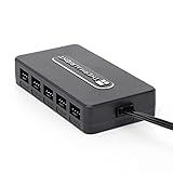
- Thermalright is a Taiwanese brand with more than 20 years of development. It has a certain popularity in domestic and foreign markets and has a decisive influence in the player market. R & D product lines include: CPU air-cooled radiator, chassis cooling fan, thermal conductive silicone pad, thermal conductive silicone grease, CPU fan controller, anti falling off mounting bracket, support mounting bracket and other commodities.
- Built in strong double-sided sticker, fixed on the chassis with double-sided sticker. SATA power line direct transmission, more concise and more efficient. Maintain stable output under high load.
- Small body, large capacity. Multi line control to keep cables in order.
- This fan hub supports the installation of 10 groups of fans, making it easy to manage wiring. Strong paste installation mode, convenient SATA power line direct transmission, and safety is guaranteed.
- Support fan speed reading. (due to the limitation of PWM mainboard IC reading principle, only the speed of a single fan inserted into the red interface is recognized).
Header labels you’ll typically find
| Common header label | What it’s for | Typical fan type |
|---|---|---|
| CPU_FAN | CPU cooler fan speed monitoring/control | CPU air cooler fan (4-pin PWM common) |
| CPU_OPT | Optional extra CPU fan (often used for a second CPU fan) | Second CPU fan |
| SYS_FAN / CHA_FAN | Chassis case fans (front, rear, top) | Case fans |
| AIO_PUMP (or PUMP_FAN) | Liquid cooler pump control/monitoring | AIO pump header (not radiator fan) |
| W_PUMP+ (board-specific) | Water pump PWM control (varies) | AIO pump |
Radiator fans are not the pump
For AIO coolers, you generally connect the pump to AIO_PUMP / PUMP_FAN. You connect the radiator fans to SYS_FAN / CHA_FAN headers (or a hub).
RGB headers are separate from fan headers
If your fans are RGB, the speed cable goes to fan headers. The RGB lighting cable goes to a dedicated RGB controller/header, often labeled ARGB (5V) or RGB (12V), or to a hub included with the case.
How to Plug In Fans Correctly (Step-by-Step)
Follow this sequence once, and you’ll avoid almost every connectivity issue.
Do these 3 things before closing this tab:
1Repair Windows errors before they cause bigger problems2Fix the driver behind crashes, sound loss and screen glitches3Clear out junk files and repair common Windows errorsPrerequisites
- Have your motherboard manual or at least locate the fan header area on the board.
- Know whether each fan is 3-pin DC or 4-pin PWM.
- Check whether your fans use separate RGB connectors.
Step-by-step wiring
- Power down and unplug the PC, then press the power button once to discharge.
- Connect the CPU fan: plug your CPU air cooler fan into CPU_FAN. If you have an additional CPU fan, use CPU_OPT (if available).
- Connect the AIO pump (if you use an AIO): plug the pump lead into AIO_PUMP / PUMP_FAN. Do not plug the pump into a chassis fan header.
- Connect radiator fans: plug radiator fans into SYS_FAN or CHA_FAN headers (or the AIO fan controller/hub if your cooler includes one).
- Connect case fans:
- Front intake fans → any SYS_FAN / CHA_FAN header.
- Rear exhaust fan → any SYS_FAN / CHA_FAN header.
- Top fans → any SYS_FAN / CHA_FAN header(s).
- Repeat for all remaining fans using available fan headers or a hub (explained later).
- Connect RGB cables separately (only if your fans are RGB). Match ARGB vs RGB voltage per the header label.
- Route cables cleanly so they won’t touch blades. Use the included clips and keep slack near the front panel area.
Does it matter which SYS_FAN header you use?
Most of the time, no—any SYS_FAN/CHA_FAN header can control case fan speed in BIOS. What matters is: the fan type (3-pin vs 4-pin), and which header supports the profile you want (PWM/DC option).
Using PWM Fans vs DC (3-Pin) Fans: What Changes
Motherboards can usually run both, but they’ll behave differently if you set the header mode incorrectly.
When your fan is 4-pin PWM
Plug it into a fan header that supports PWM control. In BIOS, set the header mode to PWM. You’ll get predictable speed curves and RPM readings.
Rank #2
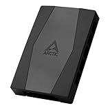
- CABLE MANAGEMENT: Case Fan Hub can be placed in housing, it's connected to motherboard with one cable, you can do without many additional cables and lay them freely in the invisible part of housing
- SYNCHRONOUS FAN CONTROL: Your set PWM signal is passed on synchronously to all fans connected to the Case Fan Hub, the RPM of the first fan slot are read out and returned to your system
- EXPAND YOUR VENTILATION: Even if you don't have enough fan headers on your mainboard, the case fan hub expands your system by 9 more case fan slots
- EXTERNAL POWER SUPPLY: The fans are powered directly from your power supply via Sata Power, there is no voltage loss at the fan speed and smooth, smooth operation is made possible
- TECHNICAL DETAILS: Output: 10 x 4-pin PWM Socket, Output Current: up to 1 A per Port, Input: SATA Power + 4-pin Fan Header, Input Current: up to 4.5 A, Dimensions: 55.6 x 86.3 x 14.3 mm, Weight: 50 g
When your fan is 3-pin DC
Plug it into a SYS/CHA header and set that header mode to DC in BIOS (if there’s an option). If you set PWM mode for a DC fan, you may see fans that don’t respond correctly or only run at one speed.
Free tools Windows power users keep installed
One-click scans. No signup required.
Mixing 3-pin and 4-pin on different headers
You can absolutely mix fan types. Just match each header’s mode in BIOS to the fan you plugged in.
Radiator Fans (AIO) and Where They Should Connect
AIO setups can be confusing because there are typically two different systems: the pump and the radiator fans.
Correct AIO connections
- Pump → AIO_PUMP / PUMP_FAN (mandatory for monitoring/control).
- Radiator fans → SYS_FAN / CHA_FAN (or the AIO’s included PWM splitter/hub).
How many headers for radiator fans?
Common cases:
- Single radiator fan connector in the AIO bundle: AIO includes a splitter so you can connect multiple radiator fans to one motherboard header.
- Separate fan cables for each radiator fan: plug each one into a separate SYS/CHA header for finer control.
Edge case: “CPU_FAN” vs AIO fan header behavior
Many boards let you assign fan control sources (CPU temp vs liquid temp) depending on the cooler. If your radiator fans are connected to SYS_FAN, set the control profile to a relevant sensor (CPU package temp is the usual fallback).
Fan Hubs, Splitters, and Fan Controllers: When You Need Them
If you have more fans than headers, you’ll use a hub. The good practice is matching the hub’s features to your fan type and monitoring needs.
Rank #3

- SATA to 3 x 3 pin / 4 pin pwm 12V pc case fan power adapter cable,use 15 pin sata connection power supply to power,for 3 x 3pin or 4pin (pwm connector) pc chassis fans, which can reduce the load of the motherboard, increase the service life of the motherboard, and ensure the PWM speed regulation function.
- SATA 15pin to 3 pin / 4 pin pwm 12V pc case fan power adapter cable,motherboard can only provide the accurate speed measurement value of one fan, so only one 4pin fan has pwm speed regulation function
- SATA to 3pin 4pin fan adapter compatible standard 3-pin and 4-pin fans,when 3pin fan is inserted no speed regulation function, only have pwm function,fans will be operated at the fixed voltage of 12V
- Input: 15-pin sata male sata connector typically used in pc for power Output: three 3/4-pin male fan connectors
- High quality black sleeved cable,24AWG, tinned copper conductor,length is approx 27cm/10.5 inches
Passive fan splitters (3-pin)
These typically just replicate power to multiple fans. They often work best for 3-pin DC fans, but RPM monitoring may be limited because you’ll only see the RPM from one connector (depending on the splitter design).
PWM fan splitters (4-pin)
PWM splitters replicate the PWM signal across multiple 4-pin fans. You may still get RPM monitoring issues if only one fan’s tach signal is connected to the motherboard header.
Active fan hubs (recommended for lots of fans)
An active hub often provides proper buffering and sometimes individual control/monitoring. Look for hubs that explicitly support PWM, and check whether they’re compatible with your fan models.
Brand examples you might run into
- Corsair: fan control is commonly done via hubs/controllers like Commander Pro/Commander Core and related wiring logic.
- NZXT: many NZXT builds use fan control modules paired with their ecosystem.
- Thermaltake and others: commonly offer fan hubs that reduce header usage.
Basic hub wiring rules
- Plug the hub’s control input into a single motherboard fan header.
- Connect fan power/speed cables to the hub’s fan ports.
- Confirm the hub expects PWM or DC. Set the motherboard header mode accordingly.
- In BIOS, you’ll often see one header RPM even though multiple fans run, depending on tach wiring.
Addressable RGB vs Non-RGB Fans (Don’t Mix the Cables)
Many fans ship with two separate connectors: one for speed (3-pin/4-pin) and one for RGB (often 3-pin 5V ARGB).
Quick wins for a faster PC:
Clear out junk files and repair common Windows errorsFree Scan →Scan for outdated or missing drivers - takes under a minuteDriver Scan →Repair Windows errors before they cause bigger problemsFix Now →How to avoid the most common RGB mistake
- ARGB headers are usually labeled 5V and often use a 3-pin 5V connector (often 5V-D-G).
- RGB headers are usually labeled 12V and often use a 4-pin connector.
If you plug ARGB into a 12V RGB header (or vice versa), lighting can fail—or in worst cases, hardware can be damaged.
Rank #4
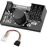
- Supports 6pcs 4 Pin PWM Fans (Fans not included, Not compatible with 3-pin/2-pin fans)
- Flexible Power Supply Input: Compatible with both SATA 12V and DC 5.5×2.5mm (5525) 12V input, allowing flexible power options
- Maximum total power output: 60W (5A@12V), with each port supporting up to 2A current while total combined current shall not exceed 5A
- Adjustable PWM duty cycle: 1%–99%
- Package include: a 4 Pin 12V PWM Fan Speed Controller ONLY
BIOS/UEFI Setup After You Plug Everything In
After wiring, verify the fan headers are detected, then configure sensible curves.
Check header detection
- Go into BIOS/UEFI and look for a Hardware Monitor or Fan Control screen.
- Confirm CPU_FAN RPM (and AIO_PUMP RPM if applicable) shows a non-zero RPM.
Set PWM/DC mode correctly
For each SYS/CHA header you used, set mode:
- 4-pin fans → PWM
- 3-pin fans → DC
Use sensible fan curves
A practical starting point for many builds:
- Choose a control source: CPU Temperature for CPU-linked chassis fans, or Motherboard Temperature if you prefer stability.
- Set a low-speed minimum that still starts reliably (PWM minimum often works well at 20–40% depending on fan model).
- Make the fan ramp steeper once temperatures exceed the midrange.
- Test under load for a few minutes and adjust so the curves feel right.
Silence fan warnings while you test (temporary)
Some BIOS versions let you disable the “CPU fan failure” alarm. Avoid leaving it disabled long-term—fix the underlying wiring or header assignment first.
Independent reader supportYour contribution helps us test, update, and keep practical guides available for everyone.Troubleshooting: Fans Aren’t Spinning or BIOS Says N/A
Use this checklist in order. The goal is to identify whether the problem is the header, the cable seating, fan mode, or a controller/hub.
Outdated Drivers Are Slowing You Down
One free scan finds every outdated or missing driver and matches the right update for your exact hardware.Free scan · exact hardware matchPC Slower Than It Used to Be?
A free scan shows the junk files, broken settings and background clutter dragging Windows down - then fixes them in one click.Free scan · Windows 10 & 11Fan is detected but not spinning
- Check orientation: fan connectors only fit one way for 4-pin PWM.
- Confirm BIOS header mode: PWM vs DC mismatch can cause “runs only at a single point” behavior.
- Increase minimum duty cycle: if you set PWM minimum too low, some fans won’t start. Raise it in steps (example: bump by 5–10%).
Fan spins, but RPM shows 0 or N/A
- On hubs/splitters, RPM may be reported only from one fan or not at all. Try connecting the fan directly to the motherboard header.
- Inspect the tach signal wire seating (especially on 4-pin connectors).
- If you’re using a splitter, swap to a different splitter port or try a different fan cable.
CPU_FAN warning won’t clear
- Confirm your CPU cooler fan is on CPU_FAN, not SYS_FAN.
- If your board supports CPU_OPT, don’t move your primary fan there.
- Try reseating the connector and verify the BIOS fan header mode is compatible.
Only one group of fans works (hub/controller issue)
- Verify the hub has power (some use SATA power).
- Check hub input: motherboard header mode (PWM vs DC) must match hub expectation.
- If your hub supports tach passthrough, confirm it’s connected to the correct header type.
Fans start randomly or ramp unpredictably
- Check that you didn’t mix a control profile between headers (some boards allow per-header assignment).
- If using software (like motherboard fan tools), ensure you’re not fighting the BIOS settings. Prefer one source of control.
Common Mistakes That Cause Wobbly RPM Readings or No Spin
- Plugging the AIO pump into SYS_FAN: some boards need AIO_PUMP/PUMP_FAN for monitoring.
- Using the wrong RGB header type: 5V ARGB vs 12V RGB mismatch.
- Setting PWM/DC incorrectly for a 3-pin DC fan.
- Using too many passive splitters or powering too many fans incorrectly—fan start/torque can suffer.
- Leaving cables loose near blades: even a small touch can cause intermittent RPM drops.
Recommended Wiring Layout for a Typical ATX Case
Most builds look like this: one CPU cooler fan (or two via CPU_OPT), plus front intake, rear exhaust, and two top exhaust fans.
Example 6-fan layout (airflow-friendly)
This is a common arrangement for an ATX case with no special radiator rules:
Best Value

- 8-way fan splitter board for powering, controlling and monitoring multiple fans, transmits PWM signal from PC motherboards or optional NA-FC1 fan controller to all connected fans
- 4-pin (for 5V and 12V fans) and S-ATA (for 12V only) inputs can be used simultaneously (power via S-ATA, RPM & PWM via 4-pin), safety fuses provide protection against overcurrent and short-circuits
- Up to 54W total power via S-ATA (12V fans only) and 24W via 4-pin interface, ideal both for 12V PC case fans and 5V applications (with Noctua 5V fans that include USB power adaptor cables)
- Easy installation on any magnetic surface such as steel PC case panels thanks to four strong mag-nets, included NA-EC1 input cable for connection to motherboard fan headers
- Full compliance with all applicable safety standards (EN 62368-1, EN 55035, EN 55032, UL-507), CE, UKCA and UL certification, renowned Noctua quality backed up by a 6 year manufacturer’s warranty
- Front: 2× intake fans
- Rear: 1× exhaust fan
- Top: 2× exhaust fans
- CPU cooler: 1× fan
Header mapping example
- CPU_FAN → CPU cooler fan
- SYS_FAN1 → Front intake fans (use a PWM splitter if they’re separate)
- SYS_FAN2 → Rear exhaust fan
- SYS_FAN3 → Top exhaust fans (split if needed)
If you have an AIO instead of air, use AIO_PUMP for the pump and move radiator fan connections onto SYS/CHA headers.
FAQs
Can I plug all fans into any SYS_FAN header?
Yes in most cases—SYS_FAN/CHA_FAN headers are meant for chassis fans. Just match the header mode in BIOS to each fan type (PWM vs DC) and make sure CPU_FAN is handled correctly.
What’s actually slowing this PC down?
Pick the symptom - the matching free tool is one click away.
Do I need to plug fans into the motherboard, or can I run them from the PSU?
You can run some fans directly from controllers powered by SATA/5V/other methods, but you’ll lose motherboard-level RPM monitoring and often lose BIOS-based fan curve control. For a clean setup, motherboard headers (plus hubs) are the usual approach.
Why do my fans spin but BIOS shows 0 RPM?
Common causes are fan hubs/splitters that don’t provide tach signal to the motherboard, loose/incorrect connector seating, or a BIOS setting that expects a different signal mode. Try direct connection to isolate the issue.
What’s the difference between CPU_FAN and CPU_OPT?
CPU_FAN is typically required for the CPU cooling warning and monitoring. CPU_OPT is usually an additional CPU fan input that also supports monitoring and control.
Should I connect radiator fans to CPU_FAN?
Usually no. Radiator fans are typically controlled as chassis fans via SYS_FAN/CHA_FAN, while the pump goes to AIO_PUMP/PUMP_FAN. Some enthusiasts reroute for a specific curve, but it’s not the default best practice.
Bottom Line
Plug the CPU cooler fan into CPU_FAN, the AIO pump into AIO_PUMP / PUMP_FAN, and everything else into SYS_FAN / CHA_FAN headers or a compatible hub. Then make BIOS match each header’s control mode to your fans (PWM for 4-pin, DC for 3-pin).
If something still doesn’t behave, isolate it by connecting one fan directly to the motherboard header and verifying PWM/DC mode—most “mystery” issues come down to a mode mismatch, a hub tach pass-through limitation, or a connector that isn’t fully seated.
Quick Recap
Product prices and availability are accurate as of the date/time indicated and are subject to change. Any price and availability information displayed on Amazon at the time of purchase will apply.




