Auto baud detection is a receiver feature that measures the timing of incoming serial data and sets its baud-rate generator to match the transmitter. It commonly relies on a known synchronization character; it does not necessarily identify the rate from any arbitrary data stream.
How does a UART detect baud rate automatically?
UART communication uses framed data whose bits are transmitted at a shared rate. In a fixed-rate setup, the transmitter and receiver are configured for the same baud rate beforehand. With auto baud detection, the receiving peripheral observes a synchronization pattern, estimates the duration of its bits from signal timing, and configures its baud-rate generator accordingly. Microchip describes the feature as enabling the receiver to determine and synchronize to the transmitter’s baud rate (Microchip, Auto-Baud Feature).
As an Amazon Associate I earn from qualifying purchases.
The basic idea is consistent, but the details are not: a peripheral may count clock cycles over a character, measure intervals between signal edges, or use another hardware-specific method. The resulting measurement is used to set the receive timing; it is not a universal algorithm shared by every UART.
Why is 0x55 often used as a sync character?
The byte 0x55, which represents the ASCII letter “U,” has alternating bits. Those repeated transitions give a receiver multiple timing edges to measure, making it a useful calibration pattern. In one Microchip implementation, measurement begins on a specified edge and ends at the fifth falling edge; another describes averaging bit time from falling edges and writing a corresponding value to the baud-rate register (Microchip, Auto-Baud Detection; Microchip, Auto-Baud Feature).
#1 Best Overall

- Dual-Core Performance Up to 240 MHz: Run sensor processing, wireless communication, automation logic and connected-device tasks on a 32-bit dual-core ESP32 platform designed for responsive embedded and IoT projects
- Built-in Wi-Fi and Bluetooth 4.2: Connect to 2.4 GHz Wi-Fi networks or use Bluetooth Classic and BLE for wireless sensors, smart devices, remote controls, home automation and other connected projects
- Flexible Power-Saving Modes: ESP32 power-management features support dynamic clock scaling and low-power operating modes, helping developers reduce energy use in compatible sensing, monitoring and connected-device applications, suitable for battery-powered Internet of Things (IoT) devices.
- USB-C Programming with CP2102: Connect through USB-C for power, sketch uploads and serial monitoring, while GPIO, UART, SPI and I2C interfaces support sensors, displays, motor drivers and other modules (USB-C cable not included)
- Over-the-Air Update Support: Configure OTA functionality through a compatible ESP-32 software framework to update deployed firmware over Wi-Fi without reconnecting the board by USB for every revision
0x55 is an example, not a universal requirement. ST’s STM32 USART material describes modes that use patterns such as 0x55 or 0x7F, as well as patterns based on the start of a character. The edges used for measurement depend on the selected mode (STMicroelectronics, Auto baud rate detection).
Does auto baud detection need a sync character?
Many implementations need a known synchronization character or frame so the receiver has predictable transitions to time. A receiver generally cannot infer a reliable rate from any arbitrary stream: data may contain long runs without transitions, and the peripheral’s detection logic may only recognize specified patterns. Check the MCU documentation for the exact input sequence it accepts.
Rank #2
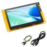
- 【Powerful ESP32-S3 Development Board】 Solve complex IoT and embedded development needs with this 4.3 inch ESP32-S3 display board. Built-in dual-core Xtensa LX7 processor with WiFi and Bluetooth 5.0 provides strong performance for smart devices, HMI projects, and DIY applications.
- 【4.3 Inch IPS High-Resolution Display】 Featuring an 800×480 IPS LCD screen, it delivers clear images, wide viewing angles, and smooth visual performance. Ideal for dashboards, control panels, data monitoring, and interactive display projects.
- 【Rich Interfaces for Flexible Expansion】 Equipped with Micro SD card slot, camera interface, SPI, UART, I2C, and GPIO expansion ports. Easily connect sensors, modules, and peripherals to build various embedded projects.
- 【Supports LVGL & Multiple Development Environments】 Compatible with Arduino IDE and ESP-IDF, supporting LVGL graphics framework for creating smooth touch interfaces, animations, and professional UI designs with ease.
- 【Complete Resources & Reliable Support】 Includes detailed pin definitions, user guides, and example programs to help beginners and developers get started quickly. A versatile choice for learning, prototyping, and embedded product development.
Calibration also has a defined interval. Some peripherals pause ordinary receive processing while measuring and signal completion or an error through status flags or interrupts. For example, Microchip’s EUSART documentation describes the feature as automatic baud-rate detection and calibration; its exact state behavior belongs to that peripheral (Microchip, Auto-Baud Detect).
What varies between UART auto-baud implementations?
| Implementation detail | What can vary |
|---|---|
| Synchronization input | Accepted patterns may include 0x55, 0x7F, or specified edge sequences; consult the relevant peripheral documentation. |
| Measurement method | The peripheral may count clock cycles over a character, measure bit or edge intervals, or use timer/input-capture hardware. |
| Receiver behavior during calibration | Normal receive processing may pause; completion and error reporting depend on device-specific flags or interrupts. |
| Configuration limits | Supported word length, operating mode, clock source, oversampling, and valid baud range vary by product family. |
ST’s application note covers hardware and software approaches using a specific STM32 configuration; it is an implementation example, not a universal UART specification (STMicroelectronics, AN4908).
Rank #3

- Powerful ESP32-S3 MCU: Equipped with an ESP32-S3R8 dual-core processor running up to 240 MHz, paired with 8MB PSRAM and 16MB Flash. Compatible with Arduino, MicroPython, and ESP-IDF for flexible embedded development
- Built-In 2MP GC2145 Camera: Integrated GC2145 2MP camera supports basic photo capture. Capture images directly from the board for embedded prototyping, camera testing, and DIY development projects
- Touchscreen & Audio Interaction: Features a 1.83-inch 320×240 capacitive touchscreen, onboard microphone, and speaker. Supports intuitive touch control and voice interaction for a more engaging development experience
- Wi-Fi & Bluetooth 5 Connectivity: Built-in 2.4GHz Wi-Fi and Bluetooth 5 support wireless communication for connected development projects. The onboard wireless connectivity is suitable for IoT applications, prototyping, and project testing
- UART & USB Type-C Interfaces: Features USB Type-C for power and programming, plus a UART interface for connecting external controllers and peripherals. Compatible with Arduino and ESP-IDF for flexible embedded development
What should you check in your microcontroller manual?
- The synchronization byte or edge pattern required, and whether the transmitter must send it before normal data.
- How to enable detection and whether the UART must be in a particular mode or use a specified word length.
- Which clock source, oversampling setting, and baud-rate range are supported.
- How the peripheral reports a completed measurement, invalid pattern, or overflow, and whether it can receive data during calibration.
Those details determine whether auto baud detection fits a design and how the sender and receiver should coordinate the initial exchange.
Quick Recap
Best Value

- Product Description: This is an entry-level RISC-V MCU ESP32-C6 development board that integrates Wi-Fi 6, Bluetooth 5, and IEEE 802.15.4 (Zigbee 3.0 and Thread). Compact yet powerful, it features a rich set of peripheral interfaces and can be used in smart home, industrial automation, healthcare, consumer electronics, and other fields
- ESP32 Development Board: Utilizing the ESP32-C6-WROOM-1-NX series module, it features a RISC-V 32-bit single-core processor supporting up to 160MHz and 8MB of built-in Flash
- Comprehensive peripheral interfaces include SPI, UART, I2C, I2S, LED PWM, and SDIO. Pinout compatible with the ESP32-C6-DevKitC-1 development board, it supports a wide range of peripheral expansion devices for enhanced ease of use
- Multiple protocols: Supports Wi-Fi 6, Bluetooth 5, and IEEE 802.15.4 (Zigbee 3.0 and Thread). Its Bluetooth Low Energy subsystem supports Bluetooth 5 (LE) and Bluetooth Mesh
- User-friendly design: The onboard CH343 serial port and CH334 USB hub enable simultaneous USB and UART use and development via a single Type-C port
Rank #4
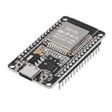
- ESP32 CP2012 USB C (Type-C) core board, it has 30 pins
- ESP32 integrates antenna, switches, RF balun, power amplifiers, low noise amplifiers, filters and power management modules
- This board is used with 2.4GHz dual-mode WiFi and wireless chips using 40nm TSMC low-power technology.
- There are two buttons integrated, one is to reset, and the other is to make the module enter the halberd program mode. The 30 pins on both sides of the development board are convenient for developers to connect and use
- Support many kinds of interfaces such as UART/SPI/I2C/PWM/DAC/ADC.
Product prices and availability are accurate as of the date/time indicated and are subject to change. Any price and availability information displayed on Amazon at the time of purchase will apply.




