Do these 3 things before closing this tab:
1Scan for outdated or missing drivers - takes under a minute2Clear out junk files and repair common Windows errors3Fix the driver behind crashes, sound loss and screen glitchesAn ESP32 relay can turn on a PC remotely by briefly closing the same low-voltage circuit as the case’s power button. It does not need Wake-on-LAN: the relay acts on the motherboard’s power-switch header instead of sending a network packet. The method depends on the board, wiring and firmware, and the cited documentation does not verify the title’s $3 price.
How the remote power-button method works
A desktop case’s power button is a momentary switch connected to the motherboard’s front-panel header. A relay wired across the power-switch pins can imitate that action: when commanded, it closes the circuit briefly, then opens it again. The PC responds as though someone had pressed the case button.
As an Amazon Associate I earn from qualifying purchases.
This is different from Wake-on-LAN (WoL). ESPHome’s WoL button sends a network magic packet addressed using the computer’s MAC address; the relay method operates the physical power-button circuit. See ESPHome’s Wake-on-LAN Button documentation.
This provides a way to request startup when the computer is shut down, but it is not universal. The motherboard must respond to its power-switch header, the relay contacts must be wired to the correct pins, and the ESP32 must be powered and reachable. The cited device guides do not establish compatibility with every PC.
#1 Best Overall

- Relay supports Normally Open and Normally Closed
- Relay supports High-level Trigger or Low-Level Trigger selectable by a jumper
- Relay with Optocoupler Isolation
- Relay with Terminal Blocks for both Input and Output Interface
- Relay with two LED Indicators: power (green LED), the relay status (red LED)
Choose the board that matches your setup
| Option | Form factor and programming | Documented I/O and state sensing | What to verify |
|---|---|---|---|
| Sinilink XY-WPCE PCIe computer remote | Dedicated PCIe-style computer remote; follow the device’s configuration and programming instructions. | GPIO5 simulates the power press, GPIO10 reads the case-button input, and GPIO12 provides a power-status signal. | Exact model and revision, pin mapping, and fit with your PC. Its documentation does not establish a universal price or motherboard compatibility. |
| ESPHome Devices ESP32 Relay x1 | Generic one-relay ESP32-WROOM-32E board; its six-pin programming header is used for serial flashing. The micro-USB port is for power, not serial flashing. | GPIO16 controls the relay. COM, NO and NC terminals are documented; the guide does not document PC power-state sensing. | Board revision, programming-header pinout, relay behavior, and whether the selected contacts suit the motherboard’s switch header. |
| ESPHome Devices ESP32 Relay x2 | Generic two-relay board; use the specific device page’s programming instructions. | Additional relay option; the cited material does not establish a universal PC power-state input mapping. | Exact board revision, pinout and configuration before wiring. |
See the device pages for the Sinilink PCIe Computer Remote (XY-WPCE), ESP32 Relay x1 and ESP32 Relay x2. Do not assume that two boards with similar names or appearances share the same pinout.
Wire the relay as a momentary power-button press
- Identify the motherboard’s power-switch pins. Consult the motherboard manual and locate the front-panel header’s power-switch pair. Do not guess based on connector position or wire color.
- Use the relay’s isolated contact pair. Connect the normally open contact (NO) and common contact (COM) across the same two pins used by the case power button. The relay should close that pair briefly, not apply ESP32 voltage to the header.
- Keep the case button available if desired. The XY-WPCE guide documents a case-button input on GPIO10. A generic relay board may not provide an equivalent input; check its wiring and configuration rather than assuming it can preserve case-button behavior.
- Keep this project on the low-voltage side. The relay contacts here are for the PC’s motherboard button header, not for switching mains power.
Configure a short pulse and a safe startup state
Make the relay action momentary: activate it for about 0.5 seconds, then turn it off. ESPHome’s GPIO switch documentation includes a 500 ms example for simulating a button, and the XY-WPCE guide uses a 0.5-second pulse. Many motherboards interpret a press lasting five seconds or longer as a forced shutdown, so do not leave the relay on as a persistent switch.
Rank #2
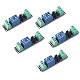
- Original Songle Relay
- 30VDC 250VAC Load:The power switch is compatible with 10A 250VAC and 10A 30VDC load.
- Optocoupler Isolator:3V/3.3V power relay module supports photocoupler isolation control.
For the dedicated XY-WPCE, follow its documented configuration: GPIO5 performs the simulated power press, with GPIO12 available as a power-status signal. For a generic ESP32 Relay x1, the device page assigns its relay to GPIO16. Adapt the configuration to the exact board and pin mapping; do not copy GPIO numbers from one model to another.
Set the relay’s boot behavior to inactive and test its electrical state through reset and startup. The XY-WPCE guide includes an on-boot relay-off action to avoid a press during restart or Wi-Fi loss. However, ESPHome notes that GPIO pull-ups can be active at reset before firmware takes control. A firmware setting alone may not prevent a brief activation on every board. See ESPHome’s GPIO Switch documentation.
Rank #3

- Programmable Relay Module 8 Channel with ESP32 BLE Development Board for Smart Home Control Secondary Development Projects DC5-30V
- The on board ESP32-32E module with large capacity 4M Byte Flash, supports the use of development tools and provide reference programs in the development environment.
- On board 8 circuit 5V relay, output switch , suitable for controlling loads with working voltage within AC 250V and DC 30V.
- The I/O ports and UART program download ports of the ESP32 module are all exported, making it convenient for secondary development.
- On board ESP32 module programmable buttons and reset buttons, on board 1 programmable LED and relay indicator light.
Flash the ESP32 without damaging it
Initial programming depends on the board. Some boards need a USB-to-serial adapter and jumper wires; others have their own documented programming method. Check the exact board’s header and voltage requirements before connecting anything. ESPHome’s physical connection guide describes serial wiring and boot mode, including GPIO0 for devices that require it. Match the adapter voltage to the device: ESPHome warns that supplying 5 V to hardware expecting 3.3 V can destroy it.
Do not connect an open device to mains electricity while flashing it. For this PC project, connect only the ESP32 board’s low-voltage relay contacts to the motherboard’s power-button header.
Rank #4
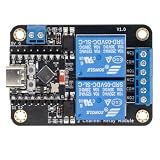
- Direct ESP32-C3 Plug-and-Play Design: Seamlessly connects with ESP32-C3 development boards without complex wiring. Ideal for quick DIY setup of smart home automation and remote control projects. The onboard socket connects directly to the ESP32-C3's 5V, GND, GPIO5, and GPIO6 pins (power supply and dual-channel relay control signals).
- ESPHome & Home Assistant Ready: Fully compatible with ESPHome and Home Assistant platforms. Includes GitHub documentation and practical code examples for rapid integration into your smart home network.
- Versatile Power Options: Flexible power input via Type-C USB port or 5V screw terminal block, allowing reliable power delivery based on your specific setup needs.
- 4 Flexible Operating Modes: Supports Type-C power, 5V terminal power, standalone PH2.0-4Pin connection to external microcontrollers, and pin expansion for attaching extra sensors alongside the ESP32-C3.
- Reliable Low-Level Trigger: Features 2-channel low-level trigger relays for accurate and stable signal control, suitable for switching household appliances and low-voltage circuits.
Test the behavior before relying on remote access
- With the PC shut down, confirm that powering or resetting the ESP32 does not trigger the relay.
- Send one remote pulse and check that the PC responds as it does to a brief case-button press.
- Confirm the relay returns to its inactive state after the pulse.
- If using a board with a documented state signal, verify that the reported state changes as expected; do not assume a generic relay board can tell whether the PC is on.
- Test what happens after ESP32 restart or loss of Wi-Fi, since boot-time GPIO behavior is board-dependent.
What the “$3” claim does—and does not—establish
The device documentation describes hardware and configuration, not a verified current seller price. No dated listing for the exact board is established here, so $3 should not be treated as a confirmed cost. The actual project also may require a compatible board, programming adapter and jumper wires, depending on the model and how it is flashed.
Free tools Windows power users keep installed
One-click scans. No signup required.
Quick Recap
Best Value

- AC-DC switching power supply module, output switch signals, the power supply mode supports AC220V/DC5-30V
- ESP32--32E WiFi module, large capacity 4M byte flash
- ESP32 32E WIFI relay module WiFi module RST reset button and a programmable button
- The I/O port of the WIFI module and the UART program download port are led out for secondary development
- ESP32 wireless WIFI 4 channel relay module WIFI module with 1 programmable LED and relay indicator onboard
Product prices and availability are accurate as of the date/time indicated and are subject to change. Any price and availability information displayed on Amazon at the time of purchase will apply.




