Recommended Free Tools
FM feedback (FMFB) and phase-locked loop (PLL) demodulators can make an FM receiver usable at a lower carrier-to-noise ratio by limiting how much noise reaches the detection process. In a typical practical comparison reported by All About Circuits in 2026, FMFB provides about 5–7 dB of threshold extension and PLL about 2–3 dB. These are reported ranges, not guarantees for every receiver—and threshold extension is not a general improvement to output signal-to-noise ratio at high carrier-to-noise levels.
Why an FM receiver has a threshold
A conventional frequency discriminator or slope detector must handle a bandwidth comparable to the full FM signal bandwidth. That bandwidth can be much wider than the message bandwidth, so noise across a broad frequency range reaches the detector. As the input carrier-to-noise ratio falls, noise can overwhelm the wanted signal and cause abrupt degradation, including phase wrapping and large output spikes.

As an Amazon Associate I earn from qualifying purchases.
FMFB and PLL designs put a tracking loop around the detection process. Rather than simply detecting frequency across the full incoming signal bandwidth, the loop follows the signal’s changing frequency or phase. This can reduce the noise that meaningfully reaches detection and delay the onset of threshold behavior. It does not eliminate the FM threshold phenomenon.
The Tool Desk
Outbyte PC Repair FREEClear out junk files and repair common Windows errorsFree Scan →Outbyte Driver Updater FREEFix the driver behind crashes, sound loss and screen glitchesFind Drivers →How an FMFB demodulator works
In the described FMFB arrangement, the forward path contains a mixer, an intermediate-frequency (IF) bandpass filter, a discriminator, and a message lowpass filter. A voltage-controlled oscillator (VCO) returns a frequency-modulated signal through the feedback path. With sufficient loop gain, the forward path effectively reverses the VCO’s FM modulation, recovering the message.
#1 Best Overall
The VCO’s phase is the integral of its control voltage, and its instantaneous angular frequency is:
φ_ex(t) = k_vco ∫v_cont(t)dt
ω_vco(t) = ω_0 + k_vco v_cont(t)
Here, v_cont(t) is the VCO control voltage and k_vco is its frequency sensitivity. The feedback loop follows the input’s slowly changing instantaneous frequency. As a result, the discriminator sees a narrower band of noise centered around the VCO frequency, rather than noise spanning the entire FM waveform bandwidth.
Rank #2

- 32 Boards In Five Sizes: Choose 4 × 6 cm, 3 × 7 cm, 5 × 7 cm, 2 × 8 cm or 7 × 9 cm boards for compact circuits, controller interfaces, classroom soldering exercises and larger point-to-point builds
- Double-Sided FR4 For Soldered Prototypes: Approximately 1.6 mm FR4 provides a rigid base for permanent electronics builds, while pre-tinned plated-through holes provide solderable connections accessible from both sides
- Standard 2.54 mm Grid Fits Common Through-Hole Parts: Lay out resistors, LEDs, DIP sockets, pin headers, terminal blocks, sensors and jumper wires on a 0.1 in pitch, then create each required connection with soldered leads, bridges or insulated wire
- From Breadboard Test To Permanent Build: Transfer a proven circuit into a compact soldered assembly for sensor nodes, controllers, alarms and STEM demonstrations; corner mounting holes help secure finished boards in enclosures or on panels
- Set Expectations Before Soldering: These are isolated-pad perfboards with no breadboard-style buses or stripboard traces, and the kit does not include components, wire, solder or tools; plan the layout and check continuity before applying power
What the bandwidth example means
All About Circuits’ 2026 worked example uses modulation index β = 10 and loop gain factor αk_vco = 12, yielding B_IF = 0.16 B_c. This illustrates how feedback can reduce the frequency deviation presented at the IF filter and, in an idealized calculation, substantially reduce the required bandwidth. It is not a universal filter specification.
In a practical loop, the IF filter must still pass the wanted FM signal without distortion. Filter shape and order also matter: a low-order filter is generally preferred in the loop for stability, and that may require a wider bandwidth than the idealized result suggests.
Rank #3
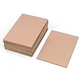
- This Copper Clad Plated Printed Board is desgined For Etch Etching Project.Single Sided (SS) Blank Copper on the Front, FR4 Bakelite on the Back.10 pcs a Pack.
- With Small Size 7x10 cm - 2.7" x 4" (W*L), 1.6mm - 0.062" Thickness, Weight in 15g 0.5oz Each.10 pieces epoxy Brown 4 x 2.7 inch
- Packed with Moisture Protecting Bag to Prevent Copper Rust. 10pcs Bare Boards Kits Delivered in their Best Conditon.
- Single-Sided Cuttable Fiber Glass and FR-4 Flame Resistant Good for Etch, Electrical, Power DIY IoT prototyping proto Projects.
How a PLL demodulator works
A basic PLL consists of a phase detector, a lowpass filter, and a VCO in a feedback loop. The phase detector compares the input phase with the VCO phase; the filtered detector output controls the VCO. When the loop is locked, the VCO follows the incoming FM signal.
Because the VCO’s frequency deviation is proportional to its control voltage, that voltage carries the recovered message. In the multiplier-type phase-detector arrangement described by All About Circuits, the locked loop has a fixed 90-degree phase difference between the input and VCO.
Rank #4

- 1. Circuit design and overload protection function can effectively cope with voltage fluctuations, ensuring stable operation of the motherboard and core components of the refrigerator
- 2. The interface position is consistent with the original motherboard. Easy installation, no need for complex modifications, greatly saving maintenance time
How FMFB and PLL compare
| Design consideration | FMFB | PLL |
|---|---|---|
| Tracking action | Tracks the input’s changing instantaneous frequency; the discriminator operates on a narrower noise band. | Tracks input phase with a phase detector and VCO; the VCO control voltage carries the recovered message. |
| VCO free-running frequency | ω_c − ω_IF, as described by All About Circuits. | Input carrier frequency ω_c, as described by All About Circuits. |
| Typical reported practical threshold extension | About 5–7 dB, reported by All About Circuits in 2026; not a guaranteed result for a particular receiver. | About 2–3 dB for most implementations, reported by All About Circuits in 2026; not a guaranteed result for a particular receiver. |
| Relative circuit complexity | More complex than the PLL in the comparison by All About Circuits. | Described as the simpler circuit by All About Circuits. |
| Design constraint highlighted | IF filtering must pass the wanted FM signal without distortion while supporting loop stability. | Requires a loop that remains locked while tracking the input; the cited explanation does not give universal filter or stability values. |
The ranges come from an explanatory article, which does not specify universal receiver designs or the experimental conditions behind those practical figures. A 1972 NASA technical report separately describes a 2 or 3 dB predetection SNR improvement over a standard discriminator for PLL or FMFB demodulation and notes that both remain subject to the FM threshold phenomenon. These figures describe different reported measures and sources, so they should not be combined into a guarantee for a new design.
Quick wins for a faster PC:
Fix the driver behind crashes, sound loss and screen glitchesFind Drivers →Clear out junk files and repair common Windows errorsFree Scan →Scan for outdated or missing drivers - takes under a minuteDriver Scan →Threshold extension is not a high-CNR SNR gain
The key benefit is near the threshold: reducing noise at the discriminator can delay failure as carrier-to-noise ratio worsens. At high carrier-to-noise ratio, the related FMFB analysis says the feedback architecture does not improve output SNR over a conventional non-feedback demodulator when both use the same post-demodulation lowpass bandwidth. Threshold extension therefore means improved tolerance of low-CNR operation in suitable systems, not better output SNR at every signal level.
Quick Recap
Best Value

- This board is especially useful for preserving a prototype or experiment you just created on a solder-less breadboard by soldering all the pieces in place.
- Suitable for a variety of MCU boards, compatible with Arduino Nano, ESP8266, NodeMCU, etc;suitable for various DIP type components; suitable for any type of Raspberry Pi GPIO breadboard PCB.
- Gold plated finish to prevent oxidation, high quality gold finish for easy soldering,and all holes are through-plated for mounting strength
- 5pcs 2.05"x3.5" PCB Solder-able Breadboard + 2pcs 2.0"x1.5" mini PCB Solder-able Breadboard for prototyping and transferring,Blue
- Lead-free and RoHS compliant for longer shelf life
What to take from the comparison
- A conventional discriminator’s need to pass broad FM bandwidth exposes it to noise well beyond the message bandwidth.
- FMFB and PLL loops track the signal and can restrict the noise that reaches the detection process, extending the usable threshold in suitable designs.
- The 2026 reported practical ranges favor FMFB for threshold extension and PLL for simpler circuitry, but neither range is a universal performance guarantee.
- The FMFB bandwidth ratio is an idealized worked example; actual filter bandwidth must also account for signal distortion and loop stability.
Product prices and availability are accurate as of the date/time indicated and are subject to change. Any price and availability information displayed on Amazon at the time of purchase will apply.




