SV Microwave’s SMPM Mini-D family groups eight RF ports in a board-to-board interconnect: an eight-port ganged cable assembly mates with an eight-port PCB connector, offered in surface-mount and edge-launch configurations. SV Microwave states that the SMPM interface supports DC to 40 GHz. That is a manufacturer’s family-level specification, not an independently measured result or a guarantee for every part and build.
What the eight-port system includes
The SMPM Mini-D family combines a compact multiport format with an SMPM interface. Its system comprises a ganged eight-port RF cable assembly and matching eight-port PCB connector halves. Grouping the connections provides a way to route multiple board-to-board RF channels through one connector arrangement; the available material does not establish a specific board-area saving.
As an Amazon Associate I earn from qualifying purchases.
SV Microwave describes the design as intended to support consistent electrical performance and mechanical alignment across channels. These are manufacturer-stated design benefits, not independently verified comparative results. SV Microwave’s SMPM Mini-D family page provides product information and technical downloads.
The Tool Desk
Outbyte Driver Updater FREEFix the driver behind crashes, sound loss and screen glitchesFind Drivers →Outbyte PC Repair FREERepair Windows errors before they cause bigger problemsFix Now →Which connector configuration fits the board?
Surface-mount
The surface-mount PCB half is intended for attachment to the board surface. SV Microwave lists the eight-port surface-mount connector as part 9311-00078. Review its datasheet and CAD resources against the board layout and assembly process before committing the footprint.
#1 Best Overall

- Includes RF EMI shield and frame, PCB testpoint for J10 and a 20 position header for P30
- Kit will improve the sensitivity of your HackRF by shielding sensitive circuitry
- Kit will make it easier to extend your HackRF's capabilities and make it easier to do board-level work
- Surface mount soldering skills and equipment are required for installation
- HackRF shown for installation demonstrational purposes only. HackRF is sold separately
Edge-launch
The edge-launch PCB half is an alternative when the RF transition is made at the board edge. The listed eight-port edge-launch connector is part 9311-00077. Choose it based on the intended board transition and physical layout rather than assuming it is interchangeable with the surface-mount version.
For either option, confirm the selected part’s footprint, mechanical details, electrical ratings, and compatibility with the cable assembly using the current part-specific documentation. SV Microwave cautions that typical specifications for the connector series may not apply to a particular part.
Rank #2
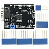
- DIY KIT MCP2515 EF02037 CAN BUS Shield Controller Board Communication Speed High CAN Module For Arduino
- Implements CAN V2.0B at up to 1 Mb/s
- SPI Interface up to 10 MHz
- Standard (11 bit) and extended (29 bit) data and remote frames Industrial standard 9 pin sub-D connector
- Two receive buffers with prioritized message storage Operating voltage: DC5-12V
Parts identified by SV Microwave
- 7093-5127: eight-port ganged cable assembly. SV Microwave’s part page describes it as an SMPM Mini-D RF female to eight 2.92 mm male, six-inch cable assembly for .085 cable. Verify the exact configuration and mating requirements in the current documentation.
- 9311-00077: eight-port edge-launch PCB connector.
- 9311-00078: eight-port surface-mount PCB connector.
Check the latest datasheet revision and confirm mating compatibility before specifying any combination. The 9311-00078 product page and 7093-5127 product page provide details and technical resources for those listed components.
What’s actually slowing this PC down?
Pick the symptom - the matching free tool is one click away.
How to evaluate it for an RF design
- Choose the board attachment: decide whether surface-mount or edge-launch better matches the PCB layout and the required transition into the board.
- Confirm the cable and mating arrangement: check the assembly configuration and connector compatibility for the specific parts, rather than relying on the family name alone.
- Check the part-level ratings: use the current datasheet for the chosen connector and cable assembly. The family’s stated DC-to-40-GHz range should not be treated as a guaranteed rating for every configuration.
- Validate the physical design: review the PCB footprint, CAD model, mechanical alignment, and installation constraints before design release.
Where SV Microwave says it may be used
SV Microwave lists test and instrumentation, bench-top testing, automated test equipment, airborne radar, and Mil-Aero among the application areas. These examples describe intended uses; they do not establish qualification for a particular instrument, aircraft, defense system, or environmental requirement. Check project-specific electrical, mechanical, and qualification needs against the applicable part documentation.
Quick Recap
Best Value

- PCB adopts 1.6mm thick double?sided board, 1.5 oz copper thickness, and the whole process of spraying tin to make sure good passing performance of large and small currents.
- Helps locate and identify potential sources of interference within the building blocks of electronic components.
- Phase noise and spectrum components can be combined with a low?noise preamplifier for measurement.
- Small size, easy to carry and store, convenient to use and with good performance.
- With 5pcs probes, can meet your use and replacement needs, very practically.
Rank #4
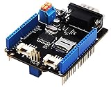
- 💎Notice: When we produced the new batch of CAN-BUS Shield V2, the wire of the back pads was embedded inside the PCB, although the wire between the pads is now not visible on the outside, the inside is still connected, if you want to change the wiring of the pads, you still need to cut the wiring in the PCB first.
- 💎CAN-BUS is a common industrial bus because of its long travel distance, medium communication speed and high reliability. It is commonly found on modern machine tools and as an automotive diagnostic bus. Thanks for CAN-BUS, makers are able to hack their cars more conveniently.
- 💎The CAN-BUS Shield V2 still uses MCP2515 as CAN-BUS controller and MCP2551 as CAN transceiver. OBD-II or CAN standard pinout can be selected by switching jumpers on DB9 interface, the default pinout is OBD-II.
- 💎We add a TF card slot for data storage and the CS pin can be either set to D4 or D5. The INT pin can also be set to D2 or D3 by switching jumpers on the back of the shield.
- 💎CAN BUS Shield Work well with Arduino UNO (ATmega328), Arduino Mega (ATmega1280/2560) as well as Arduino Leonardo (ATmega32U4) and LinkIt One.
Rank #3

- The CAN-BUS Shield compatible with arduino or Redboard can be provided with CAN-BUS capabilities and allows you to hack your vehicle.
- This shield allows you to poll the ECU for information including coolant temperature, throttle position, vehicle speed, and engine rpms. You can also store this data or output it to a screen to make an in-dash project.
- The CAN-BUS Shield Features: CAN v2.0B up to 1 Mb/s. High speed SPI Interface (10 MHz) Standard and extended data and remote frames. CAN connection via standard 9-way sub-D connector. Power can supply to Arduino by sub-D via resettable fuse and reverse polarity protection.
- It uses the Microchip MCP2515 CAN controller with the MCP2551 CAN transceiver. CAN connection is via a standard 9-way sub-D for use with OBD-II cable. Ideal for automotive CAN application. The shield also has a uSD card holder, serial LCD connector and connector for an EM506 GPS module.
- Note: A DB9 Cable is not included with this shield.----Note: This product is a collaboration with SK Pang Electronics. A portion of each sales goes back to them for product support and continued development.
Product prices and availability are accurate as of the date/time indicated and are subject to change. Any price and availability information displayed on Amazon at the time of purchase will apply.




