Do these 3 things before closing this tab:
1Clear out junk files and repair common Windows errors2Scan for outdated or missing drivers - takes under a minute3Repair Windows errors before they cause bigger problemsA 3D-printed aircraft or engine part is strong enough for jet flight only when engineers prove that its specific design, material, printing process, inspection method and service life satisfy the loads and airworthiness requirements for its intended job. Printing alone says nothing about whether a part is safe. Qualification belongs to a defined part and production process, not to the technology in the abstract.
Strength is only one part of the approval case
“Strong enough” does not mean that a test coupon survived a single pull or that a printed component feels rigid. A flight part must remain safe under every important condition expected during its approved service life. Engineers establish this through analysis, material testing, manufacturing controls, inspection and part-specific evidence.
As an Amazon Associate I earn from qualifying purchases.
The relevant questions include:
- Can the part carry limit and ultimate loads without unacceptable yielding, buckling or fracture?
- Will stiffness and dimensional accuracy keep connected systems operating correctly?
- How will repeated pressurization, vibration, thermal cycles and engine operation affect fatigue life?
- Can manufacturing defects be detected, characterized and shown to be acceptable?
- What happens if a crack starts, and how quickly could it grow?
- Can production parts be made consistently and maintained or repaired under an approved plan?
Those answers depend on the exact alloy or polymer, machine, powder or feedstock, build orientation, heat treatment, geometry, loads, environment and certification basis. The reviewed aviation guidance does not establish one universal strength number, defect-size limit or fatigue-life value that makes any printed part safe for jet flight.
Why the printed material is not automatically equivalent to wrought material
Layer-by-layer structure
Additive manufacturing builds a component in layers. The resulting microstructure and properties can vary with layer direction, laser or electron-beam parameters, thermal history, support strategy and post-processing. A part may therefore have different strength, ductility or crack-growth behavior along different axes.
#1 Best Overall

- 【Premium Carbon Fiber PETG Filament】FLASHFORGE PETG-CF is created by incorporating carbon fiber reinforcement, resulting in improved material strength and temperature resistance while maintaining the impact resistance characteristic of PETG.
- 【Stability and Reliability】Perfect for producing 3D printed parts with outstanding rigidity, exceptional dimensional stability, and superb surface quality. It is incredibly well-suited for printing a diverse range of industrial applications such as frames, drones, tools, automotive parts, and more.
- 【Clog-Free & Bubble-Free】Manufactured using clog-resistant methods to guarantee a seamless and steady printing experience with these PLA filaments. Thoroughly dried for 24 hours before packaging and vacuum sealed with desiccant to safeguard the filament from moisture and achieve precise printing.
- 【Tangle-Free and Easy for Using】Automatic winding with supplementary manual detection, to ensure that the line is tidy and less tangled to avoid possible snagging and line breakage. Additionally, FLASHFORGE PLA 1.75mm filament offers enhanced flowability and is compatible with 99% of FDM 3D printers available on the market.
- 【After-sales Support】All flashforge 3d printer filaments are provided a two-month warranty and also a 30-day Money-back if you are not satisfied. We provide 24-hour online customer service, if you have any questions regarding product issues please feel free to contact us.
Engineers must characterize the material made by the qualified process, rather than substitute handbook values for a similar conventionally manufactured alloy. Test programs commonly examine tensile and compressive strength, elongation, fracture toughness, fatigue behavior, environmental effects and variability between builds. The accepted values then apply only within the defined material-and-process envelope.
Process control is part of material control
Powder condition, storage, reuse rules, machine calibration, build-chamber atmosphere, energy settings, layer thickness, heat treatment and surface finishing can all change performance. A production specification must identify which variables are controlled, how they are recorded and what happens when a build falls outside the approved range.
FAA Advisory Circular AC 33.15-3, issued June 23, 2023, describes an acceptable means of compliance for powder-bed-fusion additive manufacturing of aircraft engine parts under 14 CFR 33.15. Its scope is specific: it should not be read as a blanket approval method for every printed aircraft structure, process or material.
Quick wins for a faster PC:
Scan for outdated or missing drivers - takes under a minuteDriver Scan →Clear out junk files and repair common Windows errorsFree Scan →Fix the driver behind crashes, sound loss and screen glitchesFind Drivers →Geometry and load paths determine where failures begin
Complex shapes can help—and hurt
Printing can consolidate several conventional pieces into one part, remove fasteners, create internal passages and produce shapes that are difficult to machine. Fewer joints can eliminate some interfaces and reduce assembly errors. However, a complex shape still has to transmit loads through continuous, well-understood paths.
Rank #2
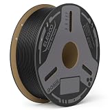
- Superior Mechanical Properties - Reinforced with carbon fiber, ELEGOO PLA-CF delivers exceptional strength and rigidity, making it ideal for producing highly durable, impact-resistant functional components.
- Better Layer Adhesion - Carbon Fiber PLA ensures tightly bonded layers for increased strength and durability, smoother surface finish with minimal layer lines, making it ideal for complex designs and high-quality prints
- High Accuracy & Less-Tangle - PLA-CF Filament is 1.75mm in diameter, accuracy +/- 0.02mm, providing consistent and smooth feeding. Each spool is machine-wound with precision-coiled layers, effectively preventing filament tangling and nozzle jams
- Clog-Free & Bubble-Free - Fully dried before packaging and vacuum-sealed to protect the filament from moisture, preventing clogs and bubbles
- Wide Compatibility - Universal compatibility with most of the common 1.75mm fdm 3d printers on the market. It’s recommended to print it with harden steel nozzle
Thin walls, sharp internal corners, abrupt section changes, unsupported overhangs and trapped powder can create stress concentrations or manufacturing uncertainty. Engineers use finite-element analysis and physical tests to verify local stresses, stiffness, buckling margins and attachment loads. They also examine whether support removal, machining or surface treatment has introduced a notch.
Orientation is a design decision
The direction in which a part is built affects layer interfaces, residual stress and the location of supports. A design that is adequate in one orientation may not meet requirements in another. Qualification therefore identifies the approved orientation or the range of orientations, along with any mandatory heat treatment and finishing operations.
Static strength does not prove fatigue safety
Aircraft and engines experience thousands or millions of stress cycles. Rotating machinery, pressure fluctuations, vibration, takeoff and landing loads, temperature changes and repeated thermal expansion can cause a crack to initiate even when a one-time static test passes.
Fatigue and crack growth
Fatigue assessment uses coupon data, component tests, analysis and, where appropriate, fracture-mechanics models. Engineers consider crack-initiation behavior, crack-growth rates, residual stresses, surface roughness and the effect of manufacturing defects. A damage-tolerance plan defines how a part remains safe if a flaw exists and how inspections can find it before it reaches a critical size.
Rank #3

- 【Carbon Fiber PLA Filament – High Strength & Rigidity】 Engineered with carbon fiber reinforcement, this PLA-CF filament delivers exceptional strength, stiffness, and impact resistance for demanding applications. Ideal for printing functional parts like brackets, gears, drone frames, and automotive components, it combines the ease of PLA with the mechanical performance of engineering materials.
- 【Superior Layer Adhesion & Smooth Matte Finish】 Achieve flawless prints with excellent layer bonding and a premium matte surface. This carbon fiber PLA minimizes warping and layer delamination, ensuring dimensional stability and a professional look for both prototypes and end-use products. The low shrinkage and smooth finish make it perfect for complex designs.
- 【Clog-Free & Bubble-Free – Pre-Dried & Vacuum Sealed】 Each spool is thoroughly dried for 24 hours and vacuum-sealed with desiccant to prevent moisture absorption. Our clog-resistant PLA-CF guarantees smooth, consistent extrusion and reliable printing without jams, blobs, or bubbles—so you can focus on creating.
- 【Precision Diameter & Wide Compatibility】 With a diameter of 1.75mm and dimensional accuracy of ±0.02mm, this carbon fiber PLA filament ensures reliable feeding and compatibility with most FFF 3D printers. The tangle-free winding further enhances your printing experience, reducing snags and interruptions.
- 【Recommended Settings & Storage Tips】 For best results, use a hardened steel nozzle (≥0.4mm) to withstand abrasion. Print at 210–230°C nozzle temperature and 50–60°C bed temperature. After printing, store the filament in a cool, dry place or resealable bag to maintain its moisture‑protected performance.
The FAA’s fatigue-and-damage-tolerance discipline treats repeated loading, fracture mechanics, probabilistic methods, testing and life-cycle planning as parts of the compliance problem. A printed component therefore needs a service-life argument tied to its actual mission and maintenance program, not a generic claim that the material is “as strong as metal.”
Life limits and inspection intervals
Some parts may be managed with a safe-life approach, in which retirement occurs before a calculated fatigue limit is reached. Others may use damage tolerance, allowing inspection to detect cracks during service. The appropriate approach depends on the part’s consequences of failure, loading spectrum, inspectability and certification basis.
Defects matter only in relation to detection and consequences
Powder-bed processes can produce pores, lack-of-fusion regions, inclusions, distortion, residual stress and surface irregularities. Not every indication causes failure, but neither can an indication be dismissed without analysis. Its size, shape, location, orientation and proximity to a high-stress region all matter.
PC Slower Than It Used to Be?
A free scan shows the junk files, broken settings and background clutter dragging Windows down - then fixes them in one click.Free scan · Windows 10 & 11Crashes, No Sound, or Screen Glitches?
Random freezes, missing sound and display glitches usually trace back to one bad driver. Find and replace yours safely.Free scan · under a minuteNondestructive evaluation
Inspection plans may use methods such as computed tomography, ultrasonic testing, radiography, dye penetrant inspection or visual examination, depending on material and geometry. Each method has a detection capability and blind spots. A method that works on an accessible, solid section may not reliably inspect a complex internal channel.
Rank #4

- 15% Carbon Fiber Reinforced PA612: Fiberon PA612-CF15 is a long-chain PA612 nylon reinforced with 15 wt% carbon fiber. It combines lower moisture sensitivity than PA6-based nylon with stronger mechanical performance than PA12-based materials, making it suitable for rigid functional parts, tooling, jigs, fixtures, and engineering prototypes.
- Strength Retention After Moisture Exposure: Typical TDS values include 91.9 MPa dry X-Y tensile strength and 83.1 MPa after the specified annealing and moisture-conditioning process. This balance makes the material useful for parts that may experience changing humidity during service.
- Heat Performance After Annealing: The heat deflection temperature reaches 175°C at 0.45 MPa after annealing at 100°C for 16 hours. Annealing also helps improve dimensional stability. HDT is a standardized test value and should not be interpreted as the continuous operating temperature of every printed part.
- Lower Moisture Sensitivity Still Requires Dry Storage: PA612-CF15 is less moisture-sensitive than PA6-based nylon but remains hygroscopic. Keep the filament below 20% relative humidity during storage and printing. Dry at 100°C for 10 hours before use if exposed to ambient humidity or if stringing, bubbles, or rough surfaces appear.
- Advanced Printer and Wear-Resistant Nozzle Required: Use an all-metal hotend, a 250–300°C nozzle, a 40–50°C build plate, and a hardened steel or ruby nozzle with the cooling fan off. A heated chamber is not required under the TDS conditions. Speeds up to 300 mm/s may be possible with a tuned profile. Before long prints, confirm smooth filament routing and unrestricted spool rotation.
The safety case must demonstrate that the selected inspection can find flaws smaller than the critical or allowable size, with appropriate probability and repeatability. It must also define acceptance criteria, inspector qualification, equipment calibration and records for every production part.
Destructive and proof testing
Coupons and witness specimens can confirm material properties and process consistency, while representative components can reveal behavior that coupons cannot capture. Proof tests may demonstrate that a finished part withstands a prescribed load or pressure. These tests support qualification, but they do not automatically qualify every geometry produced on the same machine.
Service conditions can reduce useful strength
A part that performs well at room temperature may behave differently in a hot engine, cold-soak condition or humid environment. Engineers account for temperature-dependent strength, thermal gradients, vibration, acoustic loads, corrosion, oxidation, fluid exposure and interactions among these effects.
The Tool Desk
Outbyte Driver Updater FREEScan for outdated or missing drivers - takes under a minuteDriver Scan →Outbyte PC Repair FREEClear out junk files and repair common Windows errorsFree Scan →Surface condition is especially important for fatigue. As-built surfaces can contain partially melted particles or rough features that act as crack starters. Machining, shot peening, polishing or other treatments may be required, but each operation must be controlled because it can alter dimensions, residual stress and surface integrity.
Best Value

- Outstanding Mechanical Properties - ELEGOO PETG-CF filament is made from a combination of PETG and carbon fibers. Carbon Fiber adds strength to the material, making it ideal for printing functional parts and outdoor items
- High Impact Strength - With its high impact resistance, compared to other carbon fiber materials, ELEGOO PETG-CF exhibits exceptional toughness and is less prone to fracture under external stress and impact
- Abrasion Resistance & Dimensional Accuracy - PETG-CF 3d printer filament excels in abrasion resistance and dimensional accuracy, making it ideal for gears, bearings, and structural parts that require both durability and precise fit
- Premium Print Surface - Carbon fiber brings a distinct, fine matte texture that reduces visible layer lines, ensuring a refined and professional finish perfect for both functional and aesthetic parts
- Compatibility & Tips - Universal compatibility with most of the common 1.75 mm FDM 3D printers. It’s recommended to use hardened steel nozzle with a diameter of no less than 0.4 mm at a print temperature of 240-270 °C and a hotbed temperature of 65-75 °C
How qualification turns a print into an approved flight part
- Define the intended use. Establish the aircraft or engine installation, loads, temperatures, fluids, vibration environment, failure consequences, maintenance concept and applicable airworthiness requirements.
- Freeze the design. Document geometry, tolerances, interfaces, build orientation, support strategy, material specification and all required post-processing.
- Qualify the material and process. Demonstrate that the machine, feedstock, parameters, heat treatment and finishing route produce repeatable properties and acceptable variation.
- Analyze critical behavior. Evaluate static strength, stiffness, buckling, thermal effects, fatigue, fracture and damage tolerance using validated methods and representative data.
- Test representative hardware. Use coupons, subcomponents and full-size parts where needed to correlate analysis, expose local effects and establish margins.
- Prove inspection capability. Select nondestructive methods that can find relevant defects in the actual geometry, then set acceptance criteria and inspection records.
- Establish production controls. Monitor machines, powder or feedstock, environmental conditions, calibration, traceability and deviations for each build.
- Submit the compliance evidence. The applicant and authority determine whether the analyses, tests, process controls and continued-airworthiness instructions satisfy the applicable approval basis.
- Control changes after approval. A new machine, parameter set, supplier, orientation, heat treatment or repair method may require additional substantiation rather than being treated as an automatic equivalent.
Conventional and additive designs must be compared on requirements
| Requirement | What engineers examine in an additive part | Why a conventional comparison can mislead |
|---|---|---|
| Material and process control | Powder or feedstock condition, machine parameters, thermal history, heat treatment and build-to-build variation | A wrought or cast material specification does not automatically describe printed microstructure |
| Load paths and stress concentration | Layer orientation, thin sections, internal corners, supports, interfaces and local residual stress | Part consolidation may remove joints but introduce new geometric hot spots |
| Static strength and stiffness | Directional properties, dimensional accuracy, buckling and attachment loads | A coupon result may not represent the finished geometry |
| Fatigue and crack growth | Mission cycles, surface condition, defect population, crack-growth data and inspection intervals | Single-load strength says little about long-term cyclic behavior |
| Defects and inspection | Which flaws can occur and whether the chosen nondestructive method can reliably detect them | Inspectability can be harder in enclosed channels and intricate lattice regions |
| Environment | Temperature, vibration, corrosion, oxidation, fluids and thermal cycling | Room-temperature tests may not cover engine service conditions |
| Certification and support | Approval evidence, traceability, maintenance, repair and configuration control | A successful prototype or demonstration flight does not establish a fleet-wide approval |
What real aircraft examples do—and do not—show
GE has reported FAA-cleared 3D-printed components for commercial engines, including the T25 sensor housing for GE90 engines and fuel nozzles for the LEAP engine. These examples demonstrate that a specifically qualified printed component can enter service. They do not mean that the FAA approved every printed part, that every alloy or process transfers automatically, or that an arbitrary printed structural component is ready to fly.
NASA’s aviation coverage from approximately 2018 reported that only two or three printed structural metallic parts had then been FAA-certified for flight and that none were safety-critical. That was a historical snapshot, not a current count. Its lasting lesson is to distinguish a demonstrated, program-specific application from broad claims about fully printed aircraft.
NASA researcher Karen Taminger summarized the priority in the article: “Safety is always the number one goal. So, the Federal Aviation Administration (FAA) has asked us to help them with a certification process for 3D manufacturing and the resulting parts.”
Recommended Free Tools
Spaceflight guidance is useful context, not an aircraft rule
NASA-HDBK-5026, with an active baseline dated August 12, 2024, addresses additively manufactured spaceflight hardware. It points hardware owners toward structural factors of safety, nondestructive evaluation, propulsion life assessment and fracture control. Those engineering principles are relevant when thinking about printed parts, but the handbook is not an FAA aircraft-certification regulation and should not be presented as one.
Common shortcuts that fail
- “The material is aircraft grade, so the print is safe.” The qualified object is the material-process-design combination.
- “A strong tensile coupon proves the component.” Coupons do not capture geometry, defects, interfaces, buckling or mission spectra.
- “A prototype flew once.” A demonstration does not establish fatigue life, production repeatability or continued-airworthiness instructions.
- “Inspection found no defects.” Every inspection method has resolution limits; acceptance must be tied to critical flaw size.
- “The same settings work on another machine.” Machine condition, optics, powder history and thermal behavior can differ.
- “NASA’s space standard is the aircraft approval.” Spaceflight guidance and civil-aircraft certification have different authorities and approval bases.
A practical decision checklist
Before treating a printed part as a candidate for jet service, ask:
- What exact aircraft or engine function does it perform, and what is the consequence of failure?
- Which material, machine, feedstock, orientation, heat treatment and surface finish are being qualified?
- What loads and environmental cycles define its life?
- What data support static strength, stiffness, fatigue, fracture and damage tolerance?
- What defects can the process create, and what inspection detects them in this geometry?
- How are builds traced, deviations dispositioned and changes controlled?
- What maintenance, retirement, repair and replacement instructions will operators follow?
- Which authority and certification basis govern the approval?
If any answer is missing, the part may still be a promising prototype, but its jet-flight suitability has not been established.
Bottom line
3D printing can produce flightworthy aircraft and engine parts, but the printer is only the manufacturing tool. Airworthiness comes from a documented chain of evidence tying one design to one controlled material-and-process route, validated loads and life analysis, effective inspection, production consistency and an approved certification and maintenance plan. There is no universal strength threshold that bypasses that chain.
What’s actually slowing this PC down?
Pick the symptom - the matching free tool is one click away.
Quick Recap
Product prices and availability are accurate as of the date/time indicated and are subject to change. Any price and availability information displayed on Amazon at the time of purchase will apply.




