What’s actually slowing this PC down?
Pick the symptom - the matching free tool is one click away.
RF noise can come from the environment, unwanted emissions, or the receiver’s own circuits—and each reaches or affects a signal differently. Finding the source matters: antenna-received noise calls for a different fix than cable ingress, circuit noise, or a strong interferer that overloads the receiver.
What RF noise means
ITU-R Recommendation P.372-18 defines radio-frequency noise as “a time-varying electromagnetic phenomenon having components in the radio-frequency range, apparently not conveying information and which may be superimposed on, or combined with, a wanted signal.” The recommendation, approved September 8, 2026, addresses external radio-noise backgrounds from 0.1 Hz to 100 GHz. ITU-R Recommendation P.372-18
As an Amazon Associate I earn from qualifying purchases.
Noise is not a synonym for every unwanted RF signal. A single transmitter, spur, or other identifiable emission is interference; a large aggregate of signals can look noise-like when individual sources cannot be separated. A receiver may also generate noise internally, or admit interference through cables and structures rather than its antenna. Those are distinct problems with different remedies.
Where external RF noise comes from
External noise is energy from outside the receiver that arrives through the antenna and feeder. Its level depends on frequency, antenna pattern and placement, surroundings, and the path by which energy couples into the system. ITU-R groups these sources broadly as natural or man-made.
#1 Best Overall
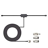
- Adhesive Mounting FM Radio Antenna 75 Ohm UNBAL FM Dipole Antenna with Universal Connector and Adapter,for Music System Indoor Radio Bluetooth Stereo Receiver AV Audio video Home Theater Receiver Tuner.
- Compatible with Yamaha, Sherwood, Pioneer, Panasonic, Onkyo, Sony, Bose Indoor Sound Radio Home Stereo Audio video Receiver, 75 ohm UNBAL.
- 10 feet / 3m Coaxial Extension Cable, Antenna Connector Interface: F Type Plug Connector; Included Connector Adapter: TV Female Socket Connector Adapter, 3.5mm Audio Plug Connector Adapter, TV Male Plug Connector Adapter;
- Easy to install; Adhesive Wall Mounting, Improves FM Radio Stereo Reception;
- Package List: 1 x Antenna, 3 x Connector Adapters;(As the Picture Shown)
Natural sources
- Atmosphere: emissions from atmospheric gases and hydrometeors, as well as lightning and other static electrical discharges.
- Earth and surroundings: emissions from land and ocean, and from obstructions within the antenna beam.
- Celestial sources: radio emissions from objects beyond Earth.
Man-made sources
- Electrical machinery, electronic equipment, and networks whose combined unintended radiation contributes to the background.
- Power transmission lines, powerline communications, and wireless power transfer.
- Industrial, scientific, and medical equipment; engine ignition systems; and inadequately shielded enclosures, transmission lines, or cables.
In a home or near obstructions, one device or a small cluster may dominate rather than a broad aggregate. Examples around low-noise amplifiers include machinery, nearby power lines, transmitters or receivers, computers, digital circuits, and switching power supplies in the same equipment. These are examples, not a universal ranking. Analog Devices AN-940
The ITU external-noise model concerns noise received through a reference antenna and feeder. A real installation can also pick up interference through other cables or structures, inadequate screening, or feeder imbalance; the recommendation cautions that these paths fall outside the scope of its external-noise data.
Noise generated inside circuits
Even with a quiet antenna input, components in the receiver create noise. The major mechanisms differ in their physical causes and frequency behavior, so the relevant one depends on the device, bias, frequency, and circuit design.
Thermal noise
Thermal, or Johnson, noise arises from the thermal motion of charge carriers in resistance. It increases with resistance, absolute temperature, and bandwidth. As a representative example—not a universal resistor value—Analog Devices gives about 4 nV/√Hz for a 1 kΩ resistor at room temperature. Analog Devices AN-940
Rank #2
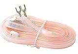
- T Shape, plug and play, easy to install and greatly improve FM Stereo Reception. 5.9 feet longer fm coax antenna cable make you receive more channels and radio stations, help you enjoy your life better.
- This 300 Ohm FM antenna provide a better radio solution for radio stereo receiver on your table top, home, office, garage, basement and so on.
- Stretch the end of the antenna as far as possible away from the device for the best reception.
- Fits all receivers with a clip or terminal FM socket. Before placing the order, please make sure your FM socket is the same as what we have mentioned.
- Package include: 1PCS antenna
Shot and avalanche noise
Shot noise reflects the discrete, random nature of current flow. Avalanche noise can occur in semiconductor devices when avalanche processes are present.
Flicker and popcorn noise
Flicker noise, often called 1/f noise, becomes more prominent toward lower frequencies. Popcorn noise consists of abrupt, random shifts or bursts in current or offset. It can matter in some semiconductors and operating conditions, but is not equally significant in every circuit. Analog Devices, “Managing Noise in the Signal Chain, Part 1”
Noise density is often expressed per square root of bandwidth for voltage or current. Independent, uncorrelated noise contributions combine by root-sum-square, not by simply adding their RMS values. Correlated sources require accounting for their relationship. Analog Devices AN-940
PC Slower Than It Used to Be?
A free scan shows the junk files, broken settings and background clutter dragging Windows down - then fixes them in one click.Free scan · Windows 10 & 11Outdated Drivers Are Slowing You Down
One free scan finds every outdated or missing driver and matches the right update for your exact hardware.Free scan · exact hardware matchReceiver effects that can masquerade as noise
Some receiver impairments arise from the interaction of signals and circuitry, not from a noisy antenna or a component’s broadband noise alone.
Rank #3

- FM Coax Antenna :Impedance:75 Ohm;Connector:F-Type Male Plug;Length:4.9ft/150cm
- Easy to Use:The FM Coax Antenna Comes with F-Type Male Connector and The AM Loop Antenna comes with 2 Pins Bare Wire ,Easy to Install,Just Insert It Into the Antenna Port On The Back of the Stereo Receiver to Receive FM and AM Radio Signal
- Portable Designed:This FM Antenna and AM Loop Antenna is Very Portable,Can Provide a Better Radio Stations to your Home, Garage, Basement, Attic, Office, etc.
- Wide Application:This FM Stereo Antenna Cord Apply to Most Home Radio Stereo Receiver,Which Provide a Better AM Radio Solution for Stereo Receiver Radios
- More Choice:The 4.9ft 75 Ohm FM Antenna Coax Coaxial Cable can Make You Receive More FM Channels and Radio Station and The AM Loop Antenna with 2-Pin Bare AM Antenna With Fold-Out Base, Easy to Install, Help You Get More Stable AM Signal
Oscillator phase noise and reciprocal mixing
Phase noise describes small fluctuations in a signal’s phase in the frequency domain. It is specified as noise power relative to the carrier in a 1 Hz bandwidth at stated frequency offsets; time-domain phase jitter is related but is a different description. If a strong nearby interferer mixes with local-oscillator phase noise, energy can spread into the wanted channel. This is reciprocal mixing, and a stronger, closer interferer is more likely to cause trouble. Analog Devices, “RF Signal Chain Discourse: Properties and Performance Metrics”
Flicker noise after down-conversion
When a receiver down-converts a wanted signal to a frequency below a device’s flicker corner before sufficient gain is applied, 1/f noise can become important. Whether it does depends on the receiver architecture and where gain and filtering occur.
Overload and intermodulation
Strong interferers can push receiver stages into nonlinear operation and create intermodulation or other spurious products that fall in the wanted channel. Consequently, filtering, front-end gain, linearity, dynamic range, and oscillator quality interact with noise performance; a lower component noise figure alone does not guarantee better reception. Analog Devices, “RF Signal Chain Discourse: Properties and Performance Metrics”
How noise affects sensitivity
Noise reduces the signal-to-noise ratio (SNR) available to the receiver. Sensitivity is the minimum input signal that meets a specified detection or demodulation requirement, so it depends on the required SNR, noise bandwidth, receiver noise figure, and the actual noise arriving at the input.
Rank #4

- Enhanced FM Reception: The fm antenna for stereo receiver ensures crystal-clear audio quality, perfect for home stereo systems and indoor radios.
- Easy Setup Design: Comes with a 5-meter coaxial cable and a retractable antenna for hassle-free installation and optimal placement.
- Strong Magnetic Base: Provides stable positioning on metal surfaces, ensuring consistent signal strength without slipping.
- Wide Compatibility: Works seamlessly with Pioneer, Onkyo, Yamaha, Marantz, Sherwood, and other leading stereo receiver brands.
- Exceptional Performance Indoors: Designed for digital HD radios and home theater setups, offering reliable signal even in urban environments.
For an idealized receiver at 290 K, Analog Devices gives this estimate:
Minimum input signal (dBm) ≈ required minimum SNR (dB) + 10 log10(noise bandwidth in Hz) + receiver noise figure (dB) − 174 dBm/Hz.
The −174 dBm/Hz term is the thermal noise density reference at 290 K, not a universal receiver floor. The estimate must be interpreted with its bandwidth, temperature, and receiver contributions in view. Analog Devices, “High Performance Narrowband Receiver Design Simplified by IF Digitizing Subsystem in LQFP”
Do these 3 things before closing this tab:
1Repair Windows errors before they cause bigger problems2Scan for outdated or missing drivers - takes under a minute3Clear out junk files and repair common Windows errorsNoise factor and noise figure
Noise factor compares input and output SNR under a defined input reference condition; noise figure is the factor expressed in decibels. The conventional standard input termination temperature is 290 K, but frequency, measurement bandwidth, and termination conditions should be stated when comparing figures. Mixer noise figures can use single-sideband or double-sideband conventions, so the convention and setup matter. Analog Devices, “System Noise-Figure Analysis for Modern Radio Receivers”
Best Value

- FM Telescopic Antenna Parameter:Impedance:75 Ohm;Connector:F-Type Male Plug;Length: 6.5" / 16.5cm; Extend length: 29.3" / 74.5cm
- Easy to Use:The 75 Ohm FM Antenna With F-Type Male Connector, Just Screw or Plug To The Antenna Socket, Very Easy to Install
- Portable Designed:This FM Antenna is Very Portable,Can Provide a Better Radio Stations to your Home, Garage, Basement, Attic, Office, etc.
- Wide Application:This FM Stereo Antenna Provide 75 Ohm FM Radio Solution for Radio, Apply to Most Home Radio Stereo Receiver,Which Provide a Better AM Radio Solution for Stereo Receiver Radios
- Make Life Better:The 75 Ohm FM Radio Antenna can Strong Signal, Make You Receive More FM Channels and Radio Station,Help You Get More Stable FM Signal, Stations for Stereo Receiver Radios
In a cascaded receiver, the earliest stages have a large influence on overall noise figure. A low-noise amplifier near the front end can therefore help, but extra gain can worsen handling of strong blockers. A meaningful comparison considers noise figure under stated conditions alongside frequency and bandwidth, antenna or source noise temperature, gain and placement, blocker linearity, and oscillator phase noise at relevant offsets.
Independent reader supportYour contribution helps us test, update, and keep practical guides available for everyone.How to identify and reduce the noise
First determine whether the problem is received through the antenna, coupled into the equipment, generated internally, or produced by a strong interferer interacting with receiver stages. Changing a component before identifying the path can leave the cause untouched—or make overload worse.
- Check whether the noise follows the antenna path. Compare reception with the antenna connected and disconnected or replaced by a properly terminated input, following the equipment’s safe operating guidance. A change points toward an external signal arriving at the antenna, though it does not by itself identify its source.
- Look for conducted or radiated ingress. If noise persists when the antenna input is terminated, inspect nearby equipment and other connections for coupling paths, including power and data cables, enclosures, screening, and feeder balance. The external-noise antenna model does not account for all such ingress.
- Separate a discrete interferer from a broad noise floor. A narrow spur or identifiable carrier suggests a particular emission; broad or noise-like energy may be an aggregate or internal noise. Use suitable spectrum or receiver measurements where available rather than assuming all unwanted energy has the same cause.
- Check for overload and reciprocal mixing. A strong nearby signal can impair reception even if the wanted channel’s own apparent noise floor looks low. Evaluate front-end filtering, linearity, gain distribution, and oscillator behavior before treating the problem solely as a low-noise-amplifier issue.
- Address the diagnosed path. For an external source, improve antenna placement or separation, shielding, or filtering as appropriate. For ingress, correct the cable, grounding, screening, or balance issue. For intrinsic noise, select and bias components for the relevant frequency and noise mechanism, and place gain appropriately in the cascade.
Measuring receiver noise figure
A standard method is the Y-factor measurement. A calibrated RF noise source provides two characterized noise-temperature states, conventionally switched on and off. Its excess noise ratio (ENR) and the measured output noise powers in both states are used to derive the device-under-test noise factor. The setup also needs an instrument to measure noise power at the DUT output; source frequency coverage, ENR, connector, calibration, and the rest of the measurement setup must match the DUT and procedure. Analog Devices, “System Noise-Figure Analysis for Modern Radio Receivers”
Quick Recap
Product prices and availability are accurate as of the date/time indicated and are subject to change. Any price and availability information displayed on Amazon at the time of purchase will apply.




