Building an LCD temperature display is a practical Arduino workshop project that combines sensor input, data processing, and real-time output on a 16×2 LCD module. By connecting a temperature sensor to an Arduino and showing the readings on a screen, you can create a compact thermometer for a desk, enclosure, classroom demo, or electronics bench.
This project introduces the core steps needed to turn raw sensor data into readable temperature values. You’ll work through the main components, wiring connections, Arduino sketch, display formatting, calibration checks, and common fixes for problems such as blank LCDs, unstable readings, or incorrect temperature values.
As an Amazon Associate I earn from qualifying purchases.
Required Components and Tools
Before wiring the circuit, gather the parts for a simple Arduino LCD temperature display. This workshop uses a standard Arduino board, a 16×2 character LCD, and a temperature sensor. The exact sensor can vary, but the common choices are the LM35 analog temperature sensor, TMP36 analog temperature sensor, or DS18B20 digital temperature sensor. For a first build, an LM35 or TMP36 is easy to use because it connects directly to an analog input pin and returns a voltage that can be converted into degrees Celsius in the Arduino sketch.
Recommended Free Tools
Core electronic components
- Arduino Uno or compatible board: The Uno is ideal for beginners, but an Arduino Nano or Mega can also be used if the pin connections are adjusted.
- 16×2 LCD module: A standard HD44780-compatible LCD works well. It has 16 columns and 2 rows for displaying the current temperature and units.
- Temperature sensor: Use an LM35, TMP36, or similar sensor. The LM35 outputs 10 mV per °C, while the TMP36 includes an offset that must be handled in code.
- 10 kΩ potentiometer: This controls the LCD contrast so the characters are readable.
- 220 Ω resistor: Used in series with the LCD backlight if your LCD module does not already include a current-limiting resistor.
- Breadboard: Provides a solderless way to assemble and test the circuit.
- Male-to-male jumper wires: Used to connect the Arduino, sensor, potentiometer, and LCD.
- USB cable: Connects the Arduino to your computer for programming and power during testing.
If your LCD includes an I2C backpack module, the wiring becomes much simpler because only four connections are needed: VCC, GND, SDA, and SCL. A bare parallel 16×2 LCD uses more Arduino pins, typically RS, E, D4, D5, D6, and D7, plus power, ground, contrast, and backlight pins. Both versions work for this project, but the parallel LCD is useful for learning how character LCD modules communicate with Arduino.
#1 Best Overall
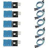
- DHT11 digital temperature and humidity sensor is a digital signal output with a calibrated temperature and humidity combined sensor.
- It uses a dedicated digital modules and acquisition of temperature and humidity sensor technology to ensure that products with high reliability and excellent long term stability.
- Sensor consists of a resistive element and a sense of wet NTC temperature measurement devices, and with a high-performance 8-bit microcontroller connected.
- The product has excellent quality, fast response, anti-interference ability, high cost and other advantages.
- The single-wire wiring scheme makes it easy to be integrated to other applications.And the simple communication protocol greatly reduces the programming effort required.
Tools and software
- Arduino IDE: Install the latest version from the Arduino website. This is where you will write, compile, and upload the sketch.
- LiquidCrystal library: This library is included with the Arduino IDE for parallel LCD modules. For I2C LCDs, install a compatible LiquidCrystal_I2C library through the Library Manager.
- Small screwdriver: Useful for adjusting the potentiometer or tightening terminal connections if your parts use screw terminals.
- Multimeter: Optional but helpful for checking 5 V, ground continuity, sensor output voltage, and backlight resistor connections.
- Computer: Any Windows, macOS, or Linux computer that can run the Arduino IDE and connect to the board over USB.
It is also helpful to keep the sensor datasheet nearby, especially if you are not using the same model shown in the workshop. Pin order is not always identical between temperature sensors. For example, an LM35 in a TO-92 package is commonly wired with the flat face forward as VCC, output, and GND from left to right, while other sensors may use a different order. Confirming the pinout before powering the circuit can prevent incorrect readings or a damaged sensor.
| Part | Typical Value or Type | Purpose |
|---|---|---|
| Arduino board | Uno compatible | Reads the sensor and controls the LCD |
| LCD module | 16×2 HD44780 | Displays temperature readings |
| Temperature sensor | LM35 or TMP36 | Measures ambient temperature |
| Potentiometer | 10 kΩ | Adjusts LCD contrast |
| Resistor | 220 Ω | Limits LCD backlight current |
How the LCD Temperature Display Works
An LCD temperature display is a simple measurement-and-output system: a temperature sensor measures the surrounding air or contact surface, the Arduino converts that sensor signal into a temperature value, and a 16×2 LCD shows the result as readable text. In this workshop build, the Arduino acts as the controller between the sensor and the display. It repeatedly samples the sensor, performs the required calculation, then refreshes the LCD with the latest reading.
The exact signal depends on the type of temperature sensor used. A common analog sensor such as the TMP36 or LM35 outputs a voltage that changes with temperature. The Arduino reads this voltage through one of its analog input pins, using its built-in analog-to-digital converter. For example, on a 5 V Arduino Uno, analogRead() converts an input voltage between 0 V and 5 V into a number from 0 to 1023. The sketch then converts that number back into voltage and applies the sensor’s formula to calculate degrees Celsius.
Do these 3 things before closing this tab:
1Clear out junk files and repair common Windows errors2Fix the driver behind crashes, sound loss and screen glitches3Repair Windows errors before they cause bigger problemsA digital sensor, such as the DS18B20 or DHT11/DHT22, works differently. Instead of sending a changing voltage, it communicates temperature data using a digital protocol. The Arduino requests a measurement, receives the value as digital data, and formats it for display. Digital sensors often simplify calibration and can be more resistant to noise over longer wires, while analog sensors are easy to understand and wire for beginner projects.
Main signal flow
- Sensor detects temperature: the sensing element responds to heat in the air, on a surface, or inside an enclosure.
- Arduino reads the signal: an analog pin measures voltage, or a digital pin receives data from a sensor library.
- Sketch converts the value: the raw reading is translated into Celsius, Fahrenheit, or both.
- LCD receives display commands: the Arduino sends characters and cursor positions to the 16×2 LCD.
- Reading appears on screen: the LCD shows a label such as Temp: followed by the current value and unit symbol.
The 16×2 LCD has two rows, with sixteen character positions on each row. In a standard parallel wiring setup, several Arduino pins are used to control the LCD: register select, enable, and four data lines in 4-bit mode. The Arduino LiquidCrystal library handles the timing details, so the sketch can use simple commands such as setting the cursor position and printing text. In many builds, a small potentiometer is also connected to the LCD contrast pin, allowing the characters to be adjusted until they are clearly visible.
The display is not continuously rewritten one pixel at a time. Instead, the Arduino sends character data to specific positions on the LCD. A typical layout places a title on the first row, such as Temperature, and the live reading on the second row, such as 23.6 C. To avoid flicker, the sketch should update only as often as needed, commonly once or twice per second, and overwrite old digits cleanly when the number of characters changes.
| Part | Job in the system |
|---|---|
| Temperature sensor | Produces a signal related to temperature |
| Arduino | Reads the sensor, calculates temperature, and controls the display |
| 16×2 LCD | Shows the measured temperature as text |
| Potentiometer | Adjusts LCD contrast for readable characters |
Because temperature changes slowly in most rooms, the project does not need high-speed sampling. A stable reading is usually more useful than a rapidly changing one. Many sketches average several sensor readings before updating the screen, which helps reduce small jumps caused by electrical noise, breadboard connections, or sensor tolerance. This makes the final display easier to read and gives the workshop project a more polished result.
Quick wins for a faster PC:
Fix the driver behind crashes, sound loss and screen glitchesFind Drivers →Clear out junk files and repair common Windows errorsFree Scan →Wiring the Temperature Sensor and LCD to Arduino
With the parts ready, the next step is to connect the temperature sensor and the 16×2 LCD to the Arduino. This section uses a common setup: an Arduino Uno, an LM35 temperature sensor, and a standard 16×2 LCD in 4-bit mode. The LCD is wired directly to Arduino digital pins, while the LM35 sends an analog voltage to one of the Arduino analog inputs.
Rank #2
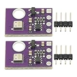
- 2pcs AHT30 High Precision Digital Temperature and Humidity Sensor Measurement Module I2C IIC Communication
- Digital temperature and humidity sensor, I2C master output, support simultaneous online access to multiple I2C electronic devices or modules.
- DC 2.0V-5V voltage can be used, voltage is easy to adapt, low power consumption, simple circuit, accurate temperature measurement point.
- Stable and fast transmission speed.
- 4P test line connection is adopted, which is convenient for users to use it quickly. Product parameters:
LM35 temperature sensor connections
Place the LM35 on the breadboard with its flat face toward you. In this position, the left pin is VCC, the middle pin is output, and the right pin is GND. Connect the left pin to the Arduino 5V pin, the middle pin to A0, and the right pin to GND. The LM35 outputs 10 mV per degree Celsius, so at 25°C the Arduino should read about 250 mV on analog pin A0.
| LM35 Pin | Connects To | Purpose |
|---|---|---|
| Left pin | Arduino 5V | Sensor power |
| Middle pin | Arduino A0 | Analog temperature signal |
| Right pin | Arduino GND | Ground reference |
16×2 LCD connections in 4-bit mode
A standard 16×2 LCD has 16 pins. To reduce the number of Arduino pins used, connect it in 4-bit mode, using only data pins D4 to D7. The LCD also needs power, ground, contrast control, and a backlight connection. A 10 kΩ potentiometer is used to adjust the LCD contrast so the characters are visible without the display appearing fully dark.
| LCD Pin | LCD Label | Connects To |
|---|---|---|
| 1 | VSS | Arduino GND |
| 2 | VDD | Arduino 5V |
| 3 | VO | Middle pin of 10 kΩ potentiometer |
| 4 | RS | Arduino digital pin 12 |
| 5 | RW | Arduino GND |
| 6 | E | Arduino digital pin 11 |
| 11 | D4 | Arduino digital pin 5 |
| 12 | D5 | Arduino digital pin 4 |
| 13 | D6 | Arduino digital pin 3 |
| 14 | D7 | Arduino digital pin 2 |
| 15 | A / LED+ | Arduino 5V through a 220 Ω resistor |
| 16 | K / LED- | Arduino GND |
Connect one outer pin of the potentiometer to 5V and the other outer pin to GND. The center pin goes to LCD pin 3, marked VO. After powering the circuit, rotate the potentiometer slowly until the LCD shows clear character blocks or text. If the contrast is too low, the screen may look blank even when the wiring and sketch are correct.
Before connecting the Arduino to USB, inspect the breadboard carefully. Make sure all ground connections share the same rail, the LCD backlight resistor is in series with pin 15, and the LM35 is not reversed. Avoid placing 5V directly onto any LCD data pin or the LM35 output pin. Once the wiring matches the tables above, the hardware is ready for the Arduino sketch that reads A0 and sends the temperature value to the display.
Writing and Uploading the Arduino Sketch
With the LCD and temperature sensor wired to the Arduino, the next step is to create the sketch that reads the sensor voltage, converts it into a temperature value, and prints the result on the 16×2 display. The example below assumes an LM35 temperature sensor connected to analog pin A0 and a standard parallel 16×2 LCD wired in 4-bit mode using Arduino pins 12, 11, 5, 4, 3, and 2.
Open the Arduino IDE, create a new sketch, and enter the following program. The built-in LiquidCrystal library is included with the Arduino IDE, so no extra library installation is needed for this parallel LCD setup.
#include <LiquidCrystal.h>
const int sensorPin = A0;
LiquidCrystal lcd(12, 11, 5, 4, 3, 2);
void setup() {
lcd.begin(16, 2);
lcd.clear();
lcd.setCursor(0, 0);
lcd.print("Temperature");
lcd.setCursor(0, 1);
lcd.print("Starting...");
delay(1500);
}
The Tool Desk
Outbyte PC Repair FREERepair Windows errors before they cause bigger problemsFix Now →Outbyte Driver Updater FREEScan for outdated or missing drivers - takes under a minuteDriver Scan →void loop() {
int sensorValue = analogRead(sensorPin);
Rank #3
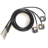
- The pluggable DS18B20 temperature probe sensor is easy to plug and can be used in a variety of environments.
- With pull-up resistor on board, the adapter module can be connected directly to most microcontrollers and it is widely used in temperature monitoring for fish tanks, equipment, machinery, greenhouses.
- Widely applications: thermostatic controls, industrial systems, consumer products, thermometers, any thermally sensitive system, etc.
- Working voltage: 3.3 ~ 5VDC, Output leads: yellow (DATA), red (VCC), black (GND)
- Measuring range: -55 ~ 125 ℃, Lead can only withstand a maximum temperature of 85 degrees
float voltage = sensorValue * (5.0 / 1023.0);
float temperatureC = voltage * 100.0;
float temperatureF = (temperatureC * 9.0 / 5.0) + 32.0;
lcd.clear();
lcd.setCursor(0, 0);
lcd.print("Temp: ");
lcd.print(temperatureC, 1);
lcd.print((char)223);
lcd.print("C");
lcd.setCursor(0, 1);
lcd.print(" ");
lcd.print(temperatureF, 1);
lcd.print((char)223);
lcd.print("F");
What’s actually slowing this PC down?
Pick the symptom - the matching free tool is one click away.
delay(1000);
}
The sketch begins by loading the LCD library and defining the analog input pin used by the sensor. The LiquidCrystal lcd(12, 11, 5, 4, 3, 2); line must match your wiring: RS, E, D4, D5, D6, and D7 in that order. If you used different Arduino pins during wiring, change these numbers before uploading. In setup(), the display is initialized as a 16-column, 2-row LCD, then a short startup message is shown.
Inside loop(), analogRead() returns a value from 0 to 1023 based on the voltage from the LM35 sensor. Since the Arduino Uno uses a 5 V reference by default, the sketch converts the ADC reading into voltage using 5.0 / 1023.0. The LM35 outputs 10 mV per degree Celsius, so mullying the voltage by 100 gives the Celsius temperature. Fahrenheit is then calculated from the Celsius value.
Uploading the sketch to the Arduino
- Connect the Arduino board to your computer using a USB cable.
- In the Arduino IDE, select your board from Tools > Board, such as Arduino Uno.
- Select the correct port from Tools > Port.
- Click Verify to compile the sketch and check for typing errors.
- Click Upload and wait for the “Done uploading” message.
After uploading, the LCD should briefly show the startup message and then update the temperature once per second. If the display shows blocks or blank characters, adjust the contrast potentiometer connected to the LCD V0 pin. If the temperature looks far too high or low, recheck the LM35 pin order: with the flat face toward you, the left pin is usually 5 V, the center pin is output, and the right pin is GND.
Displaying and Formatting Temperature Readings
Once the Arduino is reading the sensor value and the LCD library is initialized, the next step is making the output easy to read on the 16×2 display. A basic temperature value printed as a long decimal, such as 23.6875, works for testing but looks cluttered on a small LCD. A workshop-friendly display should show the temperature with a clear label, a sensible number of decimal places, and a unit symbol such as C or F.
For a typical 16×2 LCD, use the first row for a label and the second row for the live reading. For example, the first row can show Temperature:, while the second row shows 23.7 C. If you are using the Arduino LiquidCrystal library, the cursor position is controlled with lcd.setCursor(column, row). Columns start at 0, and rows are numbered 0 and 1. This lets you place text exactly where you want it rather than letting new readings run into old characters.
Rank #4
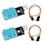
- DHT11 digital temperature and humidity sensor is a digital signal output with a calibrated temperature and humidity combined sensor.It uses a dedicated digital modules and acquisition of temperature and humidity sensor technology to ensure that products with high reliability and excellent long term stability.
- Sensor consists of a resistive element and a sense of wet NTC temperature measurement devices, and with a high-performance 8-bit microcontroller connected.
- The single-wire wiring scheme makes it easy to be integrated to other applications.And the simple communication protocol greatly reduces the programming effort required.
- Humidity Measure Range 20%-95%,humidity measurement error: +-5%; Temperature Measure Range 0-50°C,temperature measurement error: +-2 degrees.
- Working voltage: DC 3.3V-5V.Output form: digital output.
Choosing a readable format
Most temperature display projects only need one decimal place. Room temperature does not usually need to be shown as 23.684 C; 23.7 C is easier to read and more stable on the screen. The Arduino print() function can limit floating-point values to a fixed number of decimal places by adding a second argument. For example, printing a Celsius variable with one decimal place would use lcd.print(tempC, 1). For whole-number readings, use lcd.print(tempC, 0).
- 0 decimal places: best for simple displays, such as 24 C.
- 1 decimal place: a good balance for classroom and workshop projects, such as 23.8 C.
- 2 decimal places: useful for experiments, but may flicker more as the sensor reading changes.
Clearing old characters
A common LCD formatting issue happens when a new value has fewer characters than the previous value. For example, if the display changes from 100.0 C to 99.9 C, the final old character may remain visible if the row is not cleared or overwritten. Avoid calling lcd.clear() too often because it can make the screen flicker. Instead, print a few blank spaces after the value, or overwrite the entire line with a fixed-width layout.
A practical display update sequence is to set the cursor, print the label, set the cursor again, then print the formatted value and unit. If the temperature can go below zero, leave enough room for the minus sign. If your workshop sketch includes both Celsius and Fahrenheit, place one on each row, such as Celsius: 23.7 C on row 0 and Fahr: 74.7 F on row 1. Keep labels short because a 16-character row fills quickly.
| LCD Row | Example Text | Purpose |
|---|---|---|
| Row 0 | Temp Sensor | Project label or sensor name |
| Row 1 | 23.7 C | Live temperature reading |
| Row 0 | Celsius: 23.7 | Metric temperature reading |
| Row 1 | Fahr: 74.7 | Converted Fahrenheit reading |
If your LCD supports custom characters, you can create a degree symbol for a more polished display, showing 23.7 °C instead of 23.7 C. On many basic 16×2 LCDs, a custom character is more reliable than depending on extended character codes, which may vary by module. Store the custom symbol in one of the LCD’s character slots during setup, then print it between the number and the unit letter.
Finally, choose a steady refresh rate. Updating the display every 500 to 1000 milliseconds is usually enough for a temperature sensor, since room temperature changes slowly. Faster updates can make the last digit jump around and make the screen harder to read. A short delay or a timed update using millis() keeps the LCD readable while still giving the user a live temperature display.
Independent reader supportYour contribution helps us test, update, and keep practical guides available for everyone.Testing, Calibration, and Troubleshooting
After uploading the sketch and seeing text on the 16×2 LCD, test the circuit in a controlled way before mounting it in an enclosure. Power the Arduino from USB first so you can keep the Serial Monitor open while checking the LCD output. If your sketch prints the raw sensor value, voltage, or calculated temperature to Serial, compare those readings with what appears on the LCD. The two outputs should match apart from intentional formatting, such as rounding to one decimal place.
Start with a room-temperature test. Place the sensor away from your fingers, the Arduino voltage regulator, and any warm USB power adapters for a few minutes. A TMP36, LM35, DHT11, DHT22, or thermistor can all be influenced by nearby heat sources, so give the sensor time to stabilize. Compare the displayed value with a known thermometer placed close to the sensor. If the Arduino display reads consistently high or low, apply a small offset in the sketch, such as adding or subtracting 1.5°C from the calculated value.
Free tools Windows power users keep installed
One-click scans. No signup required.
Basic calibration process
- Measure at room temperature: let the sensor settle for 3 to 5 minutes, then record the LCD reading and the reference thermometer reading.
- Test a warmer point: hold your hand near the sensor without touching the leads, or place the sensor near a warm object, and watch whether the reading rises smoothly.
- Test a cooler point: move the sensor near a cool surface or a sealed cold pack wrapped in cloth, keeping moisture away from the electronics.
- Calculate the offset: if the LCD always reads 2°C high, subtract 2.0 from the calculated temperature before printing it.
- Retest: repeat the room-temperature check after editing and uploading the sketch.
For analog sensors, unstable readings are often caused by loose jumper wires, noisy power, or a floating input. Check that the sensor ground is connected to Arduino GND, the output pin goes to the correct analog pin, and the supply pin matches the sensor type. The TMP36 and LM35 are commonly powered from 5V on an Uno, while some sensor modules require 3.3V. If values jump by several degrees, try averaging mulle analog readings in the code, for example by taking 10 samples with a short delay and dividing by 10.
Best Value

- Humidity measuring range: 20% -95% and humidity measurement error: + - 5%
- Temperature measuring range: 0 degrees -50 degrees
- Operating Voltage 3.3V-5V
- Weighs about 8g each
- temperature measurement error: + - 2 degrees
| Problem | Likely cause | Fix |
|---|---|---|
| LCD is blank | No power, wrong contrast setting, or incorrect wiring | Check 5V and GND, turn the contrast potentiometer, and verify RS, E, D4, D5, D6, and D7 pins |
| LCD shows blocks only | LCD has power but is not initialized correctly | Confirm the pin numbers in the LiquidCrystal constructor match the wiring |
| Temperature reads too high | Sensor is near heat, wired incorrectly, or needs an offset | Move the sensor away from warm components and apply calibration after comparison |
| Reading is stuck | Wrong input pin or sensor output not connected | Verify the analog or digital sensor pin used in the sketch |
| Characters flicker | LCD is being cleared too often | Update only changed characters or reduce the refresh rate |
If the display works but the temperature looks unrealistic, inspect the sensor orientation carefully. Many three-pin temperature sensors have similar packages but different pin orders, and reversing power and ground can heat or damage the part. For I2C LCD modules, scan the I2C address if nothing appears; common addresses are 0x27 and 0x3F. Once the readings are stable, label the sensor position, secure the wires, and run the display for at least 15 minutes to confirm that the value remains consistent over time.
Frequently Asked Questions
Can I use an LM35, TMP36, or DHT11 sensor for this LCD temperature display?
Yes, but the wiring and Arduino code depend on the sensor type. LM35 and TMP36 are analog sensors, so they connect to an analog input such as A0 and need a voltage-to-temperature formula in the sketch. DHT11 and DHT22 are digital sensors, so they require a data pin, a library, and different code for reading temperature values.
What should I do if the 16×2 LCD lights up but shows no text?
First adjust the contrast potentiometer connected to the LCD VO pin, because text may be present but invisible. Also check that RS, E, D4, D5, D6, and D7 are connected to the same Arduino pins used in the sketch. If the backlight works but no characters appear, a wiring mismatch or incorrect LCD initialization line is usually the cause.
PC Slower Than It Used to Be?
A free scan shows the junk files, broken settings and background clutter dragging Windows down - then fixes them in one click.Free scan · Windows 10 & 11Crashes, No Sound, or Screen Glitches?
Random freezes, missing sound and display glitches usually trace back to one bad driver. Find and replace yours safely.Free scan · under a minuteHow do I make the displayed temperature more accurate?
Compare your sensor reading with a reliable thermometer at room temperature and record the difference. Add or subtract that offset in your Arduino sketch before printing the value to the LCD. For better stability, average several sensor readings instead of displaying a single raw reading.
Can I display both Celsius and Fahrenheit on the LCD?
Yes, calculate Fahrenheit from Celsius using the formula F = C × 9 / 5 + 32. On a 16×2 LCD, you can show Celsius on the first row and Fahrenheit on the second row, or show both on one row if you keep the labels short. Make sure the displayed text is cleared or overwritten properly so old characters do not remain on the screen.
Why does the temperature reading jump around or look unstable?
Small fluctuations are common with analog temperature sensors because the Arduino ADC reading can vary slightly. Use averaging in the sketch, keep sensor wires short, and make sure the sensor has a stable 5V or 3.3V supply. If the readings change dramatically, check for loose jumper wires, incorrect sensor orientation, or heat from nearby components affecting the sensor.
Bottom Line
Building an LCD temperature display is a practical Arduino workshop project that brings together sensor input, LCD output, wiring basics, and simple calibration. Once the circuit is assembled and the sketch is uploaded, small adjustments to the code and sensor readings can make the display more accurate and reliable.
Your next step is to test the setup in different environments, compare readings with a known thermometer, and refine the project with additions like Fahrenheit/Celsius switching, data logging, or alerts. Keep your wiring neat, troubleshoot one section at a time, and use this project as a foundation for more advanced Arduino monitoring systems.
Quick Recap
Product prices and availability are accurate as of the date/time indicated and are subject to change. Any price and availability information displayed on Amazon at the time of purchase will apply.




