The Tool Desk
Outbyte Driver Updater FREEScan for outdated or missing drivers - takes under a minuteDriver Scan →Outbyte PC Repair FREEClear out junk files and repair common Windows errorsFree Scan →Connect the BH1750’s VCC to the Pico’s 3V3(OUT), GND to GND, SDA to GP8, and SCL to GP9. In MicroPython, use I2C(0) on GP8 and GP9, scan for the sensor’s address, then allow time for a light reading to finish before retrieving lux.
Wire the BH1750 to the Pico
The BH1750 is a digital I2C light sensor, so it does not connect to an analog ADC input. These connections work for both Raspberry Pi Pico and Pico W:
As an Amazon Associate I earn from qualifying purchases.
| BH1750 breakout | Raspberry Pi Pico or Pico W | Purpose |
|---|---|---|
| VCC | 3V3(OUT) | Supplies the sensor at 3.3 V logic. |
| GND | Any GND pin | Provides a shared ground. |
| SDA | GP8 | I2C0 data in this example. |
| SCL | GP9 | I2C0 clock in this example. |
| ADDR | GND/low for 0x23; high for 0x5C | Selects the I2C address; check the breakout’s labeling and solder-jumper arrangement. |
Pico and Pico W GPIO use 3.3 V logic; do not feed the I2C pull-ups from a 5 V rail. Raspberry Pi’s Pico W datasheet states that its I/O voltage is fixed at 3.3 V. GP8 and GP9 are one usable I2C pin pair, not the only possible I2C pins.
Do these 3 things before closing this tab:
1Scan for outdated or missing drivers - takes under a minute2Repair Windows errors before they cause bigger problems3Fix the driver behind crashes, sound loss and screen glitchesSet up MicroPython and check the I2C address
Install the MicroPython UF2 intended for your board by following the Raspberry Pi MicroPython instructions. Then run this short scan from a MicroPython REPL or a saved script:
#1 Best Overall

- The Raspberry Pi Pico is a beginner-friendly microcontroller board that uses MicroPython to give you a taste of the Internet of Things and microcontrollers. The RP2040 is a well-designed microprocessor that can be utilized in almost any Internet of Things project. It has enough power to complete the task quickly.
- 【Raspberry Pi RP2040 Microcontroller】Raspberry Pi Pico features Dual-core ARM Cortex M0+ processor, flexible clock running up to 133 MHz. With 264KB of SRAM, and 2MB of on-board Flash memory.Supports up to 16 MB of off chip flash memory via a dedicated QSPI bus
- 【Multiple Software Support】Pico has rich and complete software support, it comes with a complete Rasberry Pi official C/C++ SDK, Micropython SDK.The programming and burning of Pico need to be carried out on the computer. Supported operating systems and computers include:Raspberry Pie with Raspberry Pi OS,Other platforms equipped with Debian based Linux system Computer with MacOS, Computers with Windows, etc.
- 【Rich Hardware Interface】Raspberry Pi Pico has 30 GPIO pins, 4 pins for analog signal input and 26 × multi-function GPIO pins, 2 × SPI, 2 × I2C, 2 × UART, 3 × 12-bit ADC, 16 × controllable PWM channels.USB 1.1 supported by host and device, The installation mode can be flexibly selected by users to facilitate welding with other development boards.
- 【Build Project in Tiny Size】Only 2.1cm*5.1cm ( as small as your thumb). Pico has been designed to use either soldered 0.1" pin-headers or can be used as a surface-mountable 'module'.
from machine import Pin, I2C

i2c = I2C(0, sda=Pin(8), scl=Pin(9), freq=100000)
print([hex(a) for a in i2c.scan()])
The code and physical wiring must use the same GPIOs. The MicroPython I2C documentation describes the I2C API and scanning attached devices. The BH1750 uses one of two 7-bit addresses: ADDR low selects 0x23, and ADDR high selects 0x5C, according to ROHM’s BH1750FVI technical note. A scan prints hexadecimal addresses, so look for 0x23 or 0x5c.
Read lux in MicroPython
Using a BH1750 driver
If a BH1750 MicroPython driver is installed on the board, create the sensor with the address reported by the scan. For the commonly used 0x23 address, a GY-302 example follows this pattern:
Rank #2

- ALL-IN-ONE INTERACTIVE DEVELOPMENT KIT: Combines a 3.5-inch 320×480 capacitive touchscreen, Mini PSP joystick, RGB LED, buzzer, and two buttons for interactive Pico projects.
- WIDE PICO COMPATIBILITY: Designed for Raspberry Pi Pico, Pico W, Pico 2, and Pico 2W series boards. Plug in a compatible Pico and start developing without soldering.
- TOUCHSCREEN & CONTROLS: Create calculators, menus, control panels, games, and graphical interfaces using the 3.5-inch capacitive touchscreen, joystick, and dual buttons.
- GPIO & POWER EXPANSION: Provides full 40-pin GPIO access plus 3.3V and 5V power interfaces, making it convenient to connect additional hardware for DIY projects.
- BUILT FOR STEM & DIY: Equipped with online documents and video tutorials for comprehensive guidance; suitable for STEAM classrooms, allowing students to make their own Pico small computer in 10 minutes, perfect for programming learning and project practice.
from machine import Pin, I2C
from utime import sleep
from bh1750 import BH1750

i2c = I2C(0, sda=Pin(8), scl=Pin(9))
sensor = BH1750(0x23, i2c)

while True:
    print(sensor.measurement)
    sleep(1)
The MicroPython BH1750 example names the GY-302 breakout and uses this driver pattern. If your scan returns 0x5c, pass 0x5c to the driver instead. The driver module must be present on the Pico for from bh1750 import BH1750 to work.
Allow the sensor to finish a conversion
In standard high-resolution mode, a reading takes about 120 ms typically; ROHM’s example sequence allows up to about 180 ms for completion. A program that reads too soon may retrieve an incomplete or stale result. High-resolution mode 2 has a typical resolution of 0.5 lux and a typical measurement time of 120 ms. In standard high-resolution mode, the raw 16-bit result is converted to lux by dividing by 1.2. If measurement-time settings are changed, apply the correction specified in ROHM’s technical note rather than assuming the same conversion factor.
Quick Recap
Best Value
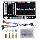
- Application: This bread board development kit which provides experimental platform for Raspberry Pi Pico.
- Convenient: It carries LED lights, buttons, buzzer and bread board, which makes the experiment circuit of Pico more convenient and convenient to takeout.
- Features: Bult-in LED lights;Bult-in Buttons;Bult-in Buzzer;Bult-in Half-size breadboard;Suitable for primary users to build DIY circuit;Size:145mmx80mm
- Package Includes: 1 x Breakout Board For Raspberry Pi Pico / Pico W;4 x M2.5x11+6 Copper Pillar;4 x M2.5 Nut;1 x Jumper wire Pack;15 x Male to Female Jumper wire; 15 x Male to Female Jumper wire; 1xTransparent Breadboard
Rank #4

- 【RP2040 Development Platform】It uses the Raspberry Pi Pico development board and is equipped with the RP2040 microcontroller, making it suitable for e-learning, programming instruction, and embedded project development.
- 【Multiple programming methods】Supports MicroPython, C/C++, and Piper Make graphical programming to meet the needs of users at different learning stages.
- 【Rich experimental modules】Includes common electronic components such as LCD1602 display module, SG90 servo motor, human body sensing module, WS2812 RGB LED strip, buzzer, and buttons, covering basic applications such as display, input, sensing, and execution control.
- 【Comprehensive learning tutorial】The kit provides detailed project tutorials and sample code to help users quickly complete circuit connections, program downloads, and experimental verification.
- 【Suitable for STEM education】Ideal for electronics beginners and school lab teaching. Through hands-on project practice, it effectively improves practical skills, logical thinking and innovation ability, making it a great choice for programming enlightenment and hobby cultivation.
Rank #3

- with pre-soldered header Raspberry Pi Pico. RP2040 microcontroller chip designed by Raspberry Pi in the United Kingdom
- Dual-core Arm Cortex M0+ processor, flexible clock running up to 133 MHz. 264KB of SRAM, and 2MB of on-board Flash memory.
- Castellated module allows soldering direct to carrier boards. USB 1.1 with device and host support. Low-power sleep and dormant modes. Drag-and-drop programming using mass storage over USB. 26 × multi-function GPIO pins.
- 2 × SPI, 2 × I2C, 2 × UART, 3 × 12-bit ADC, 16 × controllable PWM channels.Accurate clock and timer on-chip.Temperature sensor.
- Accelerated floating-point libraries on-chip.8 × Programmable I/O (PIO) state machines for custom peripheral support
Troubleshoot a scan that finds no BH1750
- Check power and ground: connect VCC to 3V3(OUT), not 5 V, and make sure the sensor and Pico share ground.
- Check the address: scan for both
0x23and0x5c. The ADDR pin or solder strap selects between them. - Check SDA and SCL: confirm SDA goes to GP8 and SCL to GP9, and that the
I2C(0)constructor names those same pins. - Inspect the breakout: examine solder joints, pull-ups, and ADDR wiring. GY-302 clones may not have identical silkscreen labels or jumper arrangements.
- Wait before reading: allow about 180 ms for a conservative first test in high-resolution mode, based on the maximum wait in ROHM’s example measurement sequence.
Product prices and availability are accurate as of the date/time indicated and are subject to change. Any price and availability information displayed on Amazon at the time of purchase will apply.




