An ESP32-S3 portable media player needs four things to work together: local storage, an I2S audio path, controls, and a safe power system. The most reliable starting point is an Espressif-supported audio development board and the official ESP-IDF audio-player example; a custom component stack gives you more freedom but adds wiring, pin-planning, compatibility, and enclosure work. A screen is optional, and battery runtime must be measured on the finished build rather than guessed.
Decide what your player needs to do
Before choosing parts, define the listening and control experience. A simple player can read files from a microSD card, output audio to headphones or a speaker, and use buttons for play, pause, track selection, and volume. You can add a display for track information and navigation, but it brings its own driver, interface, GPIO, and power requirements.
As an Amazon Associate I earn from qualifying purchases.
- Output: Choose headphones, a speaker, or both. The audio hardware must match: a line-level DAC output is not automatically powerful enough to drive headphones or a speaker.
- Library: Decide whether you need a basic test-file player or a browsable library with playlists and track information.
- Controls: Select physical buttons, a rotary encoder, touchscreen, or a combination. Set expectations for volume adjustment and long presses before implementing the interface.
- Portability: Plan the battery, charging, protection, regulators, and enclosure together. A battery connector on one board does not establish that another board accepts a battery the same way.
These choices affect the board, pin assignments, power budget, and firmware. Make them before finalizing a custom enclosure or PCB.
Choose a hardware architecture
There are two practical approaches: start with an audio development board that integrates several audio and storage functions, or assemble the functions from separate modules around an ESP32-S3 board. The official examples show that ESP32-S3 audio playback is possible, but they do not establish that every mix of board, codec, display, and storage module will work together.
#1 Best Overall

- 🔥【Dual Mode & High Performance】 The ESP32-S3 development board features integrated dual-core xtensa 32-bit LX7 microprocessor, clock speed up to 240 MHz, with 16MB Flash and 8 MB PSRAM. Perfect for Arduino IoT projects requiring stable wireless communication with ultra-low power consumption.
- 🔧【Easy Programming & Debugging】 Equipped with dual USB Type-C ports, this ESP32-S3 board supports both USB and UART modes for effortless programming, firmware flashing, and debugging.
- 🌐【Versatile Wireless Connectivity】 Built-in Wi-Fi (2.4GHz) and Bluetooth 5.0 (LE) dual-mode ensure seamless connectivity with a wide range of smart devices, making it ideal for IoT, smart homes projects.
- 🚀【Flexible Download Options】 Supports dual download methods — USB direct download or USB-to-serial download — offering flexibility and convenience for different development needs.Ideal for beginners and developers working with ESP32-S3.
- 🔋【Advanced Power-Saving Modes】 Designed for energy-efficient applications, with 3.3V SPI voltage, the ESP32-S3 board supports multiple low-power modes, allowing you to extend battery life based on different usage scenarios.
| Approach | What it involves | Main advantage | Main trade-off |
|---|---|---|---|
| Audio development board | Use a supported board with some combination of codec, microSD interface, display, or amplifier already integrated. | Less wiring and potentially less driver setup; the board may closely match an official example. | Layout and features are constrained by that board. Confirm its exact revision, interfaces, and documented hardware assumptions. |
| Custom component stack | Combine an ESP32-S3 board, microSD interface, I2S DAC or codec, output stage, controls, optional display, and a compatible power subsystem. | Lets you choose size, controls, and interfaces to suit the intended device. | Requires pin planning, electrical compatibility checks, power-integrity work, driver configuration, and more enclosure design. |
For either path, compare the actual board documentation on exposed I2S and storage connections, GPIO availability, memory, output type, battery and charging circuit, physical dimensions, and compatibility with the example firmware you intend to use. A chip’s capabilities do not guarantee that a particular board exposes every interface or has the same circuitry.
Select the controller, storage, and audio path
ESP32-S3 board
Choose an ESP32-S3 board with enough exposed GPIO for the interfaces and controls you plan to connect. Espressif’s ESP32-S3 Series Datasheet v2.24 describes two I2S interfaces and SD/MMC controller bus modes of 1-bit, 4-bit, and 8-bit. These are controller capabilities, not a promise that a given development board routes all those signals to usable pins. Check the schematic and board revision before assigning pins.
microSD and files
Use a microSD interface supported by the selected board and firmware, and verify its filesystem and capacity limits against that hardware. Espressif’s ESP Player v1.0.3 example mounts a card and uses /sdcard/test.mp3 as its documented local test file. The ADF v0.2.6 music_player example scans /sdcard for .mp3, .aac, and .wav files at one directory level. That list describes the example’s scan behavior; the decoder configuration in your chosen firmware determines what it can actually play.
The Tool Desk
Outbyte Driver Updater FREEScan for outdated or missing drivers - takes under a minuteDriver Scan →Outbyte PC Repair FREERepair Windows errors before they cause bigger problemsFix Now →Do not treat one reference board’s capacity as a platform-wide limit. The ESP-VoCat v1.2 board guide states support for microSD cards up to 32 GB on that board. Check the chosen board’s own documentation and test with the card and filesystem you plan to use.
Rank #2

- ESP32-S3-DevKitC-1-N16R8 SPI voltage: 3.3v, ESP32-S3-DevKitC-1 is an entry-level development board equipped with Wi-Fi + Bluetooth module ESP32-S3
- Most of the I/O pins on the module are broken out to the pin headers on both sides of this board for easy interfacing. Developers can either connect peripherals with jumper wires or mount ESP32-S3-DevKitC on a breadboard.
- The ESP32-S3-DevKitC development board equipped with ESP32-S3-DevKitC-1-N16R8, a general-purpose Wi-Fi + Bluetooth LE MCU module that integrates complete Wi-Fi and Bluetooth LE functions.
- ESP32-S3-N16R8 cable can be used: USB Type A to Type-C cable or CC cable Note the distinction between the commonly used USB A port to Type-C cable that can only be charged, which cannot be used for communication between YD-ESP32-S3 and the host.
- USB-to-UART Port and ESP32-S3 USB Port (either one or both), default power supply (recommended)
I2S audio and output
The audio signal path is typically ESP32-S3 I2S output → compatible DAC or codec → output stage → headphones or speaker. Espressif’s ESP-IDF v5.4 I2S documentation includes an ES8311 codec playback example, which provides a starting point when using compatible hardware. It does not mean that any ES8311 module, amplifier, or pin arrangement is interchangeable with the example’s setup.
Check whether the selected audio module supplies line-level output, headphone drive, speaker amplification, or some combination. A line-output DAC may need a separate headphone driver or speaker amplifier. Match the output stage to the transducer, confirm supply and signal compatibility from module documentation, and avoid connecting a load directly unless the module is specified to drive it.
Controls and optional display
Physical buttons and a rotary encoder can keep a first build simple. Debounce switches in firmware, define what each control does, and decide whether a long press has a distinct action. A touchscreen and display can expose track metadata and playback controls; Espressif’s ADF music_player example demonstrates a touch UI with track information, controls, playlist operation, SD initialization, DAC, and LCD setup.
Before selecting a display, verify its bus and driver, resolution needs, backlight power, and pin use against the board and audio/storage wiring. A display is an optional interface, not a requirement for audio playback.
Rank #3

- 【Low-power performance】: The AYWHP ESP32-S3 Core development board integrates a 2.4 GHz Wi-Fi and Bluetooth 5 (LE) dual-mode communication module, perfect for Arduino Internet of Things (IoT) projects.
- 【Simple programming and debugging】: The ESP32-S3 module makes it easy to program and burn in your ESP32-S3 board via dual USB Type-C ports, with a choice of USB or UART modes.
- 【Multiple Power Saving Modes】: The ESP S3 development board supports multiple low-power modes, which can be configured according to different application scenarios to provide longer battery life.
- 【Dual download modes】: The ESP S3-1 module supports both USB direct connection download and USB to serial port download, providing more flexibility and convenience.
- 【Diverse connectivity options】: The ESP32-S3-1 supports dual-mode Wi-Fi and Bluetooth 5.0 (LE) connectivity for a wide range of smart devices, making it ideal for Internet of Things (IoT) applications.
Build the firmware from an official starting point
Use ESP-IDF and begin with Espressif’s ESP Player v1.0.3 example on hardware supported by its documented assumptions. Its flow mounts microSD, initializes the codec and player, and plays a local MP3 file. This gives you a controlled way to verify the basic storage-to-audio path before adding custom controls or a display.
- Confirm the board and example match. Check the board model and revision, codec, storage connection, and any required configuration against the example documentation. Do not assume a board with the same ESP32-S3 chip uses the same audio wiring.
- Build and run the unmodified example. Follow the setup and configuration instructions that accompany that version of the example. Resolve board or configuration mismatches before adding your own features.
- Verify the local playback path. Mount the card, use the documented test-file path or adapt the firmware to the card’s actual mount point, then confirm that the chosen output produces audio.
- Add storage scanning or library behavior. If you need browsing and playlists, study the ADF v0.2.6
music_playerexample’s scan and UI approach. Its one-directory scan and listed file extensions are example behavior, not an automatic guarantee for another firmware configuration. - Implement controls. Add next, previous, pause, and volume behavior, then test physical switch debounce and any long-press action independently of the display.
- Add a display only if needed. Integrate its driver, bus, GPIO use, and backlight after playback and controls work. Check for pin conflicts and verify the screen’s power draw in the intended operating modes.
- Integrate portable power last. Once the complete audio and interface load is known, add the board-compatible battery and charging arrangement and measure current and playback duration on the assembled device.
For a custom board, keep the official example’s hardware assumptions visible while adapting pin assignments and drivers. A firmware build that compiles is not proof that the codec, SD wiring, controls, and power system are electrically compatible.
Plan battery power for the exact board
Portable power is not a generic “connect a 3.7 V cell” step. The battery, charger, protection, regulators, and board input must be compatible with one another and with the board’s documented power path. Follow the selected board’s schematic and battery specifications; do not infer safe wiring from a nominal battery voltage or from another board’s connector.
Free tools Windows power users keep installed
One-click scans. No signup required.
The ESP-VoCat v1.2 guide documents a 3.7 V battery connection for that reference design. That is a fact about the VoCat board, not a universal ESP32-S3 development-board input specification. Likewise, its stated 32 GB microSD limit applies to that board only.
Rank #4
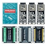
- 【ESP32-S3 PERFORMANCE】Dual-core 240MHz processor with 16MB Flash and 8MB PSRAM for IoT, AI, and machine learning projects.
- 【WIRELESS CONNECTIVITY】Onboard antenna for 2.4GHz WiFi and Bluetooth 5.0 LE — for smart home devices, no external antenna needed.
- 【LEAD-FREE GOLD EDITION DESIGN】Immersion gold (ENIG) plating for durability and conductivity. Lead-free, RoHS-compliant — for long-term prototyping.
- 【PRE-SOLDERED, PLUG-IN DESIGN】ESP32-S3 boards come with pre-soldered headers and plug directly into the included expansion and terminal boards — no soldering required.
- 【MULTI-PLATFORM COMPATIBILITY】Works with C++, MicroPython, ESP-IDF, Raspberry Pi, and STM32 — with online tutorials for quick start. Power via USB-C (5V) or VIN pin (5–12V); do not exceed 5V on the USB-C ports.
- Account for the peak demand of the ESP32-S3, codec, output stage, display backlight, and any wireless functions you actually use.
- Check the charger and protection arrangement, expected charging behavior, regulator requirements, and a safe low-voltage cutoff for the chosen cell and board.
- Measure current in relevant states, including playback, pause, screen activity, and any enabled wireless behavior.
- Measure playback duration on the completed device with the selected battery and use conditions. No measured runtime for this custom build is established by the cited official examples.
Battery runtime varies with the battery, display and backlight use, audio output, wireless activity, and conversion losses. State your test conditions if you later publish a runtime figure; do not present an estimate as a measured result.
Design the enclosure around the electronics
Lay out the enclosure after the board, battery, storage access, and controls are chosen. Leave usable access to the microSD card and the charging and programming connector. Retain the battery securely, avoid pinching wires or loading connectors mechanically, and provide appropriate openings for a speaker if one is fitted. Make sure buttons, encoder, and touchscreen remain usable without obstructing the display or audio output.
For a custom PCB, use Espressif’s ESP32-S3 Hardware Design Guidelines alongside the board and chip documentation for power, RF, memory, clocks, and layout considerations. Confirm actual pin assignment and bus configuration rather than relying on a generic ESP32-S3 pin diagram.
Validate the finished player
Test the device as a complete system, not only as a successful firmware build. Keep a record of board revision, connected modules, firmware configuration, card and test files, and power conditions; that makes failures easier to trace when changing one part at a time.
Best Value

- 【GOLD EDITION — IMMERSION GOLD PCB】The Lonely Binary Gold Edition features a black PCB with lead-free immersion gold (ENIG) plating and clear silkscreen — the signature finish of the Lonely Binary Gold Edition line. RoHS-compliant.
- 【16MB FLASH + 8MB PSRAM】Large memory capacity for OTA updates, large programs, and AI/ML tasks — more headroom than 4MB boards for data-intensive IoT and automation projects.
- 【EXTERNAL IPEX ANTENNA】External IPEX antenna can be positioned for extended WiFi and Bluetooth signal coverage — for remote applications like weather stations, robots, or enclosed builds.
- 【DUAL USB TYPE-C PORTS】Separate power and data ports for macOS, Windows, and Linux. Power via USB-C (5V) or VIN pin (5–12V); do not exceed 5V on the USB-C ports.
- 【FLEXIBLE PROTOTYPING PINS】2x40-pin GPIO headers compatible with breadboards and sensors. Supports external ToF sensors via I2C for distance sensing.
- Boot and storage: Confirm that the device starts reliably, mounts the intended card, and handles a missing or unreadable card without becoming unusable.
- File discovery: Test the directory structure and formats your firmware actually supports. If using the ADF example’s scanning behavior, confirm its one-level scan and MP3, AAC, and WAV file handling on your build.
- Playback: Check start, pause, resume, next, previous, and end-of-track behavior. Listen for dropouts, unexpected noise, or distortion at the intended output level.
- Output compatibility: Test the actual headphones or speaker with the chosen DAC/codec and output stage. Verify that the output is suitable for that load rather than assuming a line output can drive it.
- Controls and screen: Check button debounce, encoder direction, long presses, touchscreen response, track information, and behavior when the display is idle or active.
- Power and charging: Test playback while monitoring the board’s stable operation, charging behavior, and low-battery handling. Measure current and runtime with the actual battery and final enclosure configuration.
- Mechanical access: Confirm that the card, charging/programming connector, controls, and battery remain accessible and secure after assembly.
Common problems and what to check
The card does not mount or the library appears empty
Check the card interface and pin assignment against the exact board schematic, then verify the filesystem, mount point, directory location, and filename extensions expected by the firmware. The ESP Player example’s documented test path is /sdcard/test.mp3; the ADF example scans one directory level under /sdcard. A different folder layout or decoder configuration may require firmware changes.
The firmware builds but there is no sound
Trace the audio path from the I2S configuration through the codec or DAC to the output stage. Confirm that the example configuration matches the actual codec and wiring, that the output is enabled, and that headphones or speakers are connected to an output designed to drive them. The presence of I2S hardware alone does not supply an analog headphone output.
Adding a screen or module breaks another function
Recheck GPIO assignments, shared bus use, board-routed connections, power demand, and driver configuration. A display can consume pins and increase load; reserve pins for audio, storage, and controls before wiring or laying out a custom board.
Recommended Free Tools
Wireless headphones are a requirement
Verify the Bluetooth profile and firmware support for the precise board and software before designing around wireless audio. The ESP-VoCat guide labels that product’s ESP32-S3 connectivity as Bluetooth 5 LE; that does not establish generic Bluetooth headphone playback for a custom build. The ESP-BOX MP3 demo’s USB headphone behavior applies to a specific BOX-3 plus dock arrangement, not to an arbitrary ESP32-S3 assembly.
What the official examples do—and do not—establish
Espressif’s ESP-IDF v5.4 I2S documentation establishes I2S functionality for ESP32-S3 and includes an ES8311 playback example. The ESP Player v1.0.3 example provides a documented route through SD mounting, codec/player initialization, and local MP3 playback. The ADF v0.2.6 music_player example shows a more complete library-oriented pattern with SD scanning, playlist management, track information, and touch controls.
These examples are starting points tied to documented hardware and firmware configurations, not certification of every custom combination. They also do not establish a measured runtime for a custom portable player, universal capacity support, or universal Bluetooth headphone compatibility. Verify those details on the selected board and assembled build.
Quick Recap
Product prices and availability are accurate as of the date/time indicated and are subject to change. Any price and availability information displayed on Amazon at the time of purchase will apply.
What’s actually slowing this PC down?
Pick the symptom - the matching free tool is one click away.




