Free tools Windows power users keep installed
One-click scans. No signup required.
The best high-gain antenna project begins with a defined frequency, target direction, polarization, and installation limit. For most DIY radio builders, that means a published or modelled single-band Yagi—not a one-size-fits-all cut list.
A high-gain antenna is not a universal “range booster.” It is a frequency-specific directional system that concentrates transmit and receive energy in preferred directions, usually at the cost of coverage elsewhere. For a first serious build, a single-band Yagi-Uda antenna made from a published or carefully modelled plan is the most practical project: it is directional, scalable, and measurable without pretending that one set of dimensions fits every band.
As an Amazon Associate I earn from qualifying purchases.
Start with a design brief, not a cut list
Do not cut metal until these decisions are fixed. Antenna gain, impedance, pattern, polarization, and usable bandwidth all change with frequency.
- Purpose: receive-only, transmit/receive, terrestrial point-to-point, repeater work, satellite work, television, Wi-Fi, or another service.
- Exact operating frequency or band: “VHF” is not precise enough. A design for 146 MHz is not automatically suitable for 144–148 MHz, 433 MHz, Wi-Fi, or television.
- Target direction: one station, a repeater, a horizon sector, or a moving satellite.
- Polarization: horizontal, vertical, or a service-specific arrangement. A 90-degree polarization mismatch can materially weaken a link.
- Required bandwidth: a narrow single-frequency system and a whole amateur band may need different compromises.
- Physical limits: available boom length, element span, mounting height, wind exposure, roof/mast capacity, and access for maintenance.
- RF system: feed-line length, connector type, transmitter power, matching method, choke/common-mode plan, and measurement equipment.
- Rules and safety: licensing, RF-exposure evaluation, siting rules, grounding/bonding practice, and local building requirements.
If any of those is unknown, the right next step is to resolve it—not to copy a random “high gain antenna” diagram.
#1 Best Overall

- High-Gain Long-Range Coverage – 25dBi directional Yagi antenna for 2.4GHz WiFi, boosts signal strength and range for more stable, interference-free connections.
- Complete Adapter Kit Included – Comes with RP-SMA Female to SMA Female, RP-SMA Female to SMA Male, RP-SMA Male to N Female, and RP-SMA Female to RP-SMA Female adapters.
- Wide Device Compatibility – Works with routers, USB WiFi adapters, range extenders, PCI network cards, and security cameras using RP-SMA interface.
- Easy and Flexible Installation – 1.5M low-loss coaxial cable allows convenient positioning for best signal reception without complicated setup.
- Durable Outdoor Design – Weatherproof and rust-resistant construction ensures reliable performance for both indoor and outdoor use.
What gain actually tells you
Gain describes how strongly an antenna radiates or receives in a particular direction compared with a reference antenna. It does not create power, guarantee a certain number of miles, or overcome every obstruction and source of noise. The same directional behavior that helps a desired path also produces weaker directions and often deeper nulls elsewhere.
| Term | What it means | Why it matters in a project |
|---|---|---|
| dBi | Gain referenced to an ideal isotropic radiator. | Common in specifications and modelling output. |
| dBd | Gain referenced to a lossless half-wave dipole. | Often used in amateur-radio descriptions. |
| Conversion | dBd = dBi − 2.15 dB. | Always compare figures using the same reference. |
| Beamwidth | Width of the useful main lobe. | A narrower beam can reject unwanted directions but demands more accurate aiming. |
| Front-to-back behavior | How well energy from behind the antenna is reduced relative to the forward direction. | Can matter as much as headline gain when interference is behind you. |
| Bandwidth | Frequency range over which the antenna remains acceptably matched and patterned. | A high-gain design may be less forgiving away from its design frequency. |
Describe any quoted gain honestly: modelled, manufacturer-specified, or measured by a calibrated method. An SWR reading is not a gain measurement. Accurate absolute gain measurement requires controlled comparison methods and reference antennas; a casual on-air report cannot establish a precise dBi figure.
Why a frequency-specific Yagi is the right first project
A Yagi-Uda antenna uses one driven element connected to the feed line and one or more nearby parasitic elements: typically a reflector behind it and directors in front. The reflector/director arrangement shapes a forward main lobe. Adding and optimizing directors can make the array more directional, but gains become progressively harder to win as boom length, wind loading, alignment sensitivity, and construction effort rise.
The important word is specific. Element lengths, diameters, centre-to-centre spacing, boom effects, driven-element geometry, and the feed-point match interact. A two-element plan, a multi-element plan, and a plan moved to another frequency are different designs. Do not “scale by eye,” substitute arbitrary tubing, or lengthen elements until an SWR meter looks happy.
Choose a published, frequency-specific Yagi design or a reviewed antenna model that supplies all of the following:
Rank #2

- Dipole set includes 1x dipole base with 60cm RG174, 2x 23cm to 1m telescopic antenna, 2x 5cm to 13cm telescopic antenna, 1x 3m RG173 extension cable, 1x flex tripod mount, 1x suction cup mount.
- design frequency and intended bandwidth;
- element lengths and material/diameter assumptions;
- element-centre positions from a stated boom datum;
- driven-element shape and feed-point impedance;
- the required matching arrangement and its dimensions;
- polarization orientation;
- predicted pattern, forward gain, and front-to-back behavior; and
- installation assumptions, especially boom and element mounting details.
Amateur-radio project collections include beginner two-element beams, VHF beam projects, and model files that can provide a starting point. Treat model collections as starting material: verify the design, its units, assumptions, and target frequency yourself before construction.
Choose the project before buying materials
- Lock the frequency. Wavelength drives element dimensions, cable loss, connector choices, and the antenna family that makes sense.
- Match the polarization. Mount the elements in the orientation used by the intended system. For a conventional Yagi, the elements determine polarization: horizontal elements give horizontal polarization; vertical elements give vertical polarization.
- Choose the smallest design that meets the job. A shorter beam is often easier to mount, aim, survive in wind, and troubleshoot. More elements are not automatically a better installation.
- Check the mechanical envelope. Confirm element span, boom length, turning radius, mast diameter, bracket clearance, and a safe installation path before ordering stock.
- Plan the feed system and measurements. Decide where the match, choke, connector transition, weatherproofing, and analyzer calibration plane will be.
Materials: buy to the plan, not to a generic shopping list
Exact quantities and dimensions come from the selected design. The categories below prevent common omissions without implying that every Yagi uses the same parts.
Do these 3 things before closing this tab:
1Fix the driver behind crashes, sound loss and screen glitches2Clear out junk files and repair common Windows errors3Scan for outdated or missing drivers - takes under a minute- Conductive element stock of the specified diameter and alloy.
- A boom and element-to-boom mounting arrangement compatible with the design’s electrical assumptions. Use nonconductive or suitably isolated parts where the plan requires them.
- Element clamps, fasteners, insulators, and corrosion-resistant hardware appropriate to the outdoor environment.
- The specified matching and feed components; do not substitute a different matching scheme without redesigning or re-modelling.
- Coaxial cable, connectors, adapters, strain relief, and weatherproofing materials suitable for the intended frequency and outdoor exposure.
- A mast, mounting brackets, and hardware sized for the actual antenna and site.
- Hand tools, a measuring tool, and a calibrated antenna analyzer or VNA.
Build with dimensional discipline
Most disappointing home-built beams are not defeated by exotic RF theory; they are defeated by small, undocumented mechanical differences.
- Use one boom datum. Mark every element centre from the same reference end. Do not accumulate measurements from one element to the next.
- Label each element. Mark reflector, driven element, and every director before assembly. Keep a written build sheet with the as-built length and position.
- Keep geometry square. Centre elements as specified, align them perpendicular to the boom, and avoid accidental twist. A horizontal Yagi whose elements sag or rotate is no longer built to its assumed polarization and pattern.
- Preserve intentional isolation. Check whether each element is electrically bonded to or isolated from the boom in the selected design. Unintended metal contact can alter the antenna.
- Build the driven element exactly. Its gap, bend geometry, mounting, and feed connection directly affect impedance. Keep the feed point mechanically supported; do not let coax carry the strain.
- Install the specified match and choke. A balun, gamma match, hairpin, or other arrangement is part of the design, not decoration. A current/choke balun is commonly used to keep common-mode current off the outside of the feed line where appropriate.
- Weatherproof without trapping water. Provide drip loops and strain relief. Seal outdoor connector interfaces with suitable materials while avoiding a water reservoir around the feed point.
Feed line and common-mode current: the part that can erase the benefit
Feed line carries RF energy in both directions and every real cable has loss. That loss depends strongly on cable type, frequency, and run length. Select cable based on loss at the highest frequency you expect to use and the actual installed run—not on a label such as “low loss.” At higher frequencies, a cable that is acceptable for a short patch lead may be a poor choice for a long mast run.
A low SWR displayed at the radio does not prove low cable loss, resonance at the antenna terminals, the intended pattern, or useful forward gain. Loss can make an imperfect load look less objectionable at the shack end. Likewise, an antenna tuner may help a transmitter operate with some non-resonant systems, but it does not correct a wrongly dimensioned Yagi, misplaced element, poor feed-point connection, or unwanted feed-line radiation.
Rank #3

- Precision 50 Ohm Impedance: This SMA Adapters Kit engineered to maintain accurate impedance matching for minimal signal reflection and maximum power transfer in professional RF systems
- 16 in 1 RF Adapter Kit: This RF adapter kit featuring 16 combinations of UHF/BNC/N-type/F-type to SMA male/female adapters, ideal for applications from amateur radio to professional test, no need to purchase separate adapters
- Wide Application: This Coaxial Adapter Kit Seamlessly connect various RF equipmen including SWR, CB radios (PL-259/SO-239), handheld/ mobile ham radios, walkie-talkies, SDR dongles, NanoVNA analyzers, and other RF test equipment
- Military Grade Quality: These SMA connectors constructed with gold-plated brass for excellent conductivity and corrosion resistance, ensuring reliable signal transmission with minimal loss across all connections
- Multi Connector Solution: Essential SMA adapters for 5G (Verizon/T-Mobile), industrial IoT (Honeywell/Rockwell), and emergency comms (Garmin/Yaesu), solving multi-vendor connectivity with 50Ω impedance-matched interfaces
Common-mode current is another separate problem. If the outer surface of coax becomes part of the antenna system, the cable can distort the pattern, carry RF back toward equipment, and make results change when the cable is moved. Use a band-, power-, and cable-appropriate current/choke balun where the design calls for it. Do not copy an online ferrite recipe without confirming those inputs.
Quick wins for a faster PC:
Clear out junk files and repair common Windows errorsFree Scan →Scan for outdated or missing drivers - takes under a minuteDriver Scan →Measure and tune in a repeatable loop
The right tool category for this project is a NanoVNA vector network analyzer. It can make a build-and-adjust cycle much more informative than a single-frequency SWR meter. Before buying, confirm the genuine instrument’s frequency range, connector type, included calibration standards, firmware/support situation, and seller authenticity. Its label alone does not guarantee performance across your target band.
- Assemble to the chosen dimensions first. Do initial measurements without transmitting.
- Calibrate correctly. Follow the analyzer/VNA manual and calibrate for the connector/adaptor arrangement used. Calibration at one connector plane and then adding unknown adapters changes what is being measured.
- Sweep the whole intended range. Record frequency, SWR, resistance, and reactance or complex impedance. A single “good” point can hide a poor match across the operating band.
- Measure near the antenna terminals when possible. This separates the antenna from long feed-line effects. Use the same setup for comparison measurements.
- Change one variable at a time. Make a small reversible adjustment, document it, then repeat the same sweep. Do not shorten multiple elements and change the match simultaneously.
- Recheck after installation. A mast, nearby metal, routing of the coax, and final mounting height can alter results. Compare with the pre-installation record.
- Assess system behavior separately. More capable analyzers can also help investigate feed-line loss and impedance behavior; use that information to diagnose the whole installation rather than treating SWR as the only metric.
Simple tuning record
| Change | Reason | Sweep result | Keep or revert? |
|---|---|---|---|
| Baseline as built | Reference | Record full sweep and measurement plane | Keep as baseline |
| One small match adjustment | Move resistive/reactive behavior toward design target | Repeat identical sweep | Decide from data |
| One feed/choke-routing change | Check common-mode sensitivity | Compare repeatability and impedance | Decide from data |
| Installed configuration | Confirm site effects | Repeat sweep and document mounting details | Final configuration |
Validate directionality without overstating it
Once the antenna-terminal measurements are satisfactory, compare it with a known reference antenna using a controlled receive test or consistent on-air checks. Hold as many variables constant as possible: frequency, polarization, source/station, receiver settings, height, feed line, and location. Rotate the Yagi slowly and record the direction of strongest reception and the reduction away from it.
This can confirm that the antenna behaves directionally and may reveal an aiming error, but it is still an informal field check. It does not turn an SWR graph or a single signal report into a calibrated gain measurement. Label your result accordingly: “informal receive comparison,” “model prediction,” or “calibrated measurement.”
Troubleshooting branches
| Symptom | Likely area to inspect | First safe check |
|---|---|---|
| Resonant point is far from the target frequency | Wrong element length, wrong spacing, driven-element geometry, design/material mismatch | Recheck every measurement against the design sheet before cutting anything further. |
| Results change when coax is moved | Common-mode current or inadequate choke placement | Inspect feed routing and the design’s choke/balun arrangement; repeat the same sweep. |
| Good SWR but weak or inconsistent directional behavior | Pattern distortion, polarization error, feed-line radiation, nearby metal, or incorrect aiming | Verify element order, orientation, mounting surroundings, and cable routing. |
| High SWR after mounting | Mast/roof interaction, damaged connector, water ingress, altered feed geometry | Compare to the pre-installation baseline and inspect the feed point before transmitting. |
| Match is acceptable only at one narrow point | Design bandwidth limit or incorrect match geometry | Review the selected design’s expected bandwidth; do not force a narrow design to cover a much wider service. |
Stop-work safety and compliance checks
Do not install or transmit until these are addressed.
The Tool Desk
Outbyte PC Repair FREERepair Windows errors before they cause bigger problemsFix Now →Outbyte Driver Updater FREEFix the driver behind crashes, sound loss and screen glitchesFind Drivers →- Keep the antenna, mast, tools, and yourself well clear of overhead power lines. Treat every nearby line as energized.
- Plan fall protection, ladder use, dropped-object control, wind limits, and a safe way to raise long conductive elements.
- Do not assume a roof, eave, chimney, mast, or bracket can carry the antenna’s wind and ice load. Site-specific mechanical judgement—and, where needed, a qualified assessment—comes before installation.
- Use appropriate lightning, grounding, and bonding practices for the installation; disconnecting or grounding choices must follow applicable local requirements and equipment guidance.
- Evaluate RF exposure before transmitting. Keep people outside the applicable evaluated exposure region, especially near directional antennas and higher-power installations.
- For U.S. amateur-radio installations, check current FCC RF-exposure guidance, including OET Bulletin 65 and the amateur-radio supplement where applicable. Antenna structures can also trigger FCC/FAA notification or registration thresholds and local or state siting controls.
- Outside the United States, use the rules of the country and locality where the antenna is installed. U.S. guidance is not a substitute for them.
What success looks like
A successful high-gain antenna project is not necessarily the one with the largest advertised dB number. It is a documented antenna built to a valid frequency-specific design, mounted safely, fed with suitably low-loss cable, controlled for common-mode current, measured at the right reference plane, and aimed with its pattern and polarization in mind. That approach gives you a directional system you can improve intelligently—and evidence for what it actually does.
Rank #4
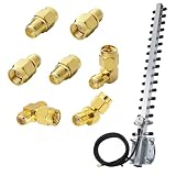
- 🚀 Boost Signal Like a Pro Includes a 2.4GHz 25dBi Yagi directional antenna with RP-SMA connector and 1.5M low-loss cable – ideal for long-range WiFi, repeater setups, or boosting weak signals in outdoor/remote areas.
- 🔁 7-in-1 SMA/RP-SMA Adapter Kit Included Straight, 45°, and 90° RF adapters plus a 3-way SMA splitter – gives you total flexibility to connect across routers, radios, FPV, SDRs, cameras, or whatever tech you're working with.
- 🎯 Directional Power, Zero Wasted Signal The Yagi antenna focuses energy in one direction for maximum range and speed – a great fit for point-to-point connections or devices far from the access point.
- 🔌 Plug and Play with Broad Compatibility Supports routers, PCI cards, USB WiFi adapters, FPV gear, Baofeng handheld radios, SDR receivers, and more – works with RP-SMA and SMA male/female interfaces.
- 🧰 Built for Tight Installs & Custom Setups Angled RF adapters (45°/90°) and compact design make it easy to install in tricky spots like corners, racks, or outdoor enclosures without stressing cables.
Frequently Asked Questions
Will a high-gain antenna double my range?
No. Gain is directional and depends on frequency, the design, installation, feed-line loss, polarization, both ends of the link, terrain, interference, and transmitter power. It cannot honestly be converted into a universal distance increase.
Does low SWR mean my antenna has high gain?
No. Low SWR only describes the match at the measurement point. It does not prove low feed-line loss, resonance at the antenna, the intended radiation pattern, or forward gain.
Do I need a balun or choke?
Use the selected design’s specified arrangement. A current/choke balun is commonly used to reduce common-mode current on the feed line, but its design must suit the target band, cable, and transmitter power.
Windows Errors? Fix Them Before They Spread
Repair common Windows errors and clear accumulated junk for a smoother, more stable PC - no reinstall needed.Free scan · no reinstallCrashes, No Sound, or Screen Glitches?
Random freezes, missing sound and display glitches usually trace back to one bad driver. Find and replace yours safely.Free scan · under a minuteIs a NanoVNA useful for tuning a Yagi?
A NanoVNA vector network analyzer is a useful category of tool for sweeping SWR and impedance across a band. Verify the actual unit’s frequency range, connectors, calibration standards, firmware/support, and seller authenticity before purchase.
The Bottom Line
Build a Yagi for one defined frequency and use case, then treat dimensions, feed line, choke, installation, and measurement as one system. Low SWR is useful diagnostic evidence; it is not proof of gain.
Quick Recap
Product prices and availability are accurate as of the date/time indicated and are subject to change. Any price and availability information displayed on Amazon at the time of purchase will apply.




