An ESP8266 can be turned into a small WiFi range extender that connects to an existing router and rebroadcasts a second wireless network for nearby devices. It is not a replacement for a mesh system or a dedicated repeater, but it can be a low-cost way to improve coverage in a workshop, garden corner, garage, or IoT test area.
Using the Arduino ecosystem, you can either write a simple sketch that bridges WiFi connections in a limited way or flash purpose-built repeater firmware that handles the job more directly. The setup typically involves an ESP8266 board such as a NodeMCU or Wemos D1 mini, a stable USB power supply, the Arduino IDE or flashing tools, and access to your main WiFi network credentials.
As an Amazon Associate I earn from qualifying purchases.
Before building one, it helps to understand the tradeoffs: the ESP8266 has one 2.4 GHz radio, limited RAM, and modest throughput, so speed and stability depend heavily on placement, signal quality, power, and firmware choice. With realistic expectations, it can still be a useful project for extending basic connectivity and learning how WiFi station and access point modes work together.
Recommended Free Tools
How an ESP8266 WiFi Range Extender Works
An ESP8266 WiFi range extender works by using the chip’s WiFi radio in two roles at the same time. One side connects to your existing router as a normal WiFi client, often called station mode. The other side creates a new WiFi network that phones, laptops, sensors, or other devices can join, called access point mode. In ESP8266 terminology this combined mode is usually called STA+AP.
#1 Best Overall

- Not only it is easy to program for this controller by using the CP2102-USB interface,but also unnecessary to press the flash and reset buttons before each flash operation.
- NodeMcu is an open source Lua based firmware for the ESP8266, ultra low cost wireless modules, development boards for rapid prototyping, integrated with ESP8266 chips.
- The ESP8266 has powerful on-board processing and storage capabilities, and can be integrated with sensors and other application-specific devices through its GPIOs.
- It is compatible with Arduino IDE,works great with the latest Mongoose IoT/Micropython.
- Modern Internet development tools can use the built-in API to instantly put your idea on the fast track.
When a device connects to the ESP8266’s access point, its traffic is received by the ESP8266 and then forwarded through the ESP8266’s station connection to the main router. Replies from the internet or local network come back through the router, reach the ESP8266, and are sent onward to the connected device. This makes the ESP8266 act like a small bridge or repeater between two wireless links, although the exact behavior depends on the firmware being used.
Repeater, extender, bridge, and NAT mode
In consumer networking, the terms range extender and repeater are often used loosely. With an ESP8266, the most common practical setup is not a perfect transparent repeater. Instead, many firmware projects use NAT, or Network Address Translation. In this arrangement, devices connected to the ESP8266 receive IP addresses from the ESP8266 itself, while the ESP8266 uses a single connection to the upstream router.
This is similar to how a home router shares one internet connection with many devices. For example, your main router might use the network 192.168.1.x, while the ESP8266 creates a second network such as 192.168.4.x. A phone connected to the ESP8266 may browse the internet normally, but some local network discovery features, file sharing, casting, or device-to-device control may not work exactly as they would on the main WiFi network.
What happens to speed and latency
The ESP8266 has only one 2.4 GHz WiFi radio, so it cannot receive from the router and transmit to a client at the exact same moment on separate radios. It must share airtime between the upstream connection and the downstream access point. As a result, throughput is usually much lower than the main router’s WiFi speed. In real use, an ESP8266 repeater is suitable for low-bandwidth tasks such as sensor nodes, smart plugs, MQTT clients, simple web access, or basic messaging, but it is not a good match for HD video streaming, gaming, or large file transfers.
- Frequency band: ESP8266 supports only 2.4 GHz WiFi, not 5 GHz or 6 GHz.
- Radio sharing: one radio handles both the router link and client devices.
- Best placement: halfway between the router and weak-signal area, but still within reliable router coverage.
- Typical use: extending coverage for IoT devices rather than replacing a commercial mesh system.
Placement has a major effect on reliability. If the ESP8266 is installed where the original WiFi signal is already very weak, it will repeat an unstable connection and clients may see dropouts. A better location is where the ESP8266 still receives a steady signal from the main router, then rebroadcasts that connection into a nearby dead spot. Antenna orientation, USB power quality, nearby metal objects, walls, and interference from other 2.4 GHz networks can all affect the final result.
At a high level, the ESP8266 range extender is a compromise: it is inexpensive, compact, and easy to experiment with in the Arduino ecosystem, but it has limited processing power, memory, and wireless capacity. Understanding that tradeoff helps set realistic expectations before choosing firmware, wiring the board, and configuring the repeater network.
Required Hardware and Software
To build an ESP8266 WiFi range extender with the Arduino ecosystem, you only need a small set of inexpensive parts, but the exact board and power setup matter. A repeater keeps the ESP8266 radio active for long periods, so unstable USB ports, weak phone chargers, or poor cables can cause random disconnects that look like software problems. Start with a known-good development board and a reliable 5 V power source before tuning firmware or network settings.
The Tool Desk
Outbyte Driver Updater FREEFix the driver behind crashes, sound loss and screen glitchesFind Drivers →Outbyte PC Repair FREERepair Windows errors before they cause bigger problemsFix Now →Recommended hardware
- ESP8266 development board: A NodeMCU ESP8266, Wemos D1 mini, or similar ESP-12E/ESP-12F based board is the easiest choice because it includes USB-to-serial, voltage regulation, and boot circuitry.
- Micro-USB cable: Use a data-capable cable, not a charge-only cable. Many upload failures in the Arduino IDE are caused by low-quality USB leads.
- Stable 5 V power supply: Use a USB power adapter rated for at least 1 A. The ESP8266 can draw sharp current peaks when transmitting, even though average consumption is much lower.
- Computer for flashing: Windows, macOS, or Linux will work as long as the correct USB serial driver is installed.
- Main WiFi router: The ESP8266 must be placed where it can still receive a usable signal from the original router, not at the edge of total coverage.
- Optional enclosure: A plastic case helps protect the board, but avoid metal boxes because they reduce WiFi signal strength.
For most readers, a NodeMCU or Wemos D1 mini is preferable to a bare ESP-01 module. Bare modules require a separate 3.3 V regulator, USB-to-serial adapter, pull-up resistors, and careful boot wiring. They can work, but they add unnecessary variables when the goal is to test repeater behavior. If you already have an ESP-01, make sure its power supply can provide enough current at 3.3 V; powering it directly from a weak USB serial adapter often causes boot loops or failed associations.
Software you may need
- Arduino IDE: Arduino IDE 2.x or 1.8.x can compile and upload ESP8266 sketches after the ESP8266 board package is installed.
- ESP8266 board package: Add the ESP8266 boards URL in Arduino IDE preferences, then install the package through Boards Manager.
- USB serial driver: Many NodeMCU boards use CH340 or CP2102 USB chips. Install the matching driver if the board does not appear as a serial port.
- Repeater firmware or Arduino sketch: You can upload a purpose-built NAT repeater firmware, or write an Arduino sketch using ESP8266 WiFi access point and station modes.
- Serial monitor: The Arduino IDE Serial Monitor is useful for checking connection status, IP addresses, and restart messages.
- WiFi analyzer app: A phone app can help inspect signal strength, channel congestion, and whether the repeated network is visible.
The software path depends on how much control you want. Arduino code is familiar and easy to modify, but a simple sketch that connects to one WiFi network and creates another does not automatically behave like a full consumer repeater. To pass traffic between the two interfaces, you need routing and usually NAT support. Some users therefore choose dedicated ESP8266 repeater firmware projects that already implement NAT, DHCP for client devices, and a web configuration page. The Arduino IDE is still useful for flashing sketches and testing hardware, but prebuilt repeater firmware may require a separate flashing tool depending on the project.
Before moving to configuration, gather the main router SSID and password, choose a new SSID for the ESP8266 repeated network, and decide where the board will be powered. The best location is usually halfway between the router and the weak-signal area, where the ESP8266 still receives a fair to strong upstream signal. If it is placed in a dead zone, it can broadcast a new network name, but it will have little useful bandwidth to repeat.
Rank #2

- The ESP8266 NodeMCU development board has a built-in 0.96-inch OLED display (128x64, SSD1306) and supports the I2C interface. It can be directly integrated without additional wiring, making it an ideal choice for quickly building ESP8266-based visual display projects
- The development board is equipped with the ESP8266 ESP-12E module, using the Tensilica Xtensa 32-bit LX106 CPU (80-160MHz), equipped with 128KB RAM and 4MB Flash, which can provide stable performance for demanding ESP8266 IoT applications
- The onboard OLED uses the I2C interface through the SDA (D6/GPIO12) and SCL (D5/GPIO14) pins on the ESP8266 NodeMCU, which can easily display real-time network status, sensor data, and other ESP8266 project information
- The ESP NodeMCU development board has built-in Wi-Fi, supports deep sleep, and is compatible with RTOS. It is ideal for low-power IoT solutions such as ESP8266 weather stations, clocks, and smart monitoring systems
- This ESP8266 development board uses a Type-C port for power and data transmission. The CH340 driver can be easily installed by searching online. It is fully compatible with Windows systems and is an ideal choice for ESP8266 beginners and professionals
Choosing Between Arduino Code and Repeater Firmware
There are two common ways to turn an ESP8266 into a WiFi extender: writing or uploading a sketch through the Arduino IDE, or flashing dedicated repeater firmware. Both use the same ESP8266 hardware, but they target different goals. Arduino-based projects are better when you want to learn, customize behavior, or combine repeating with sensors, relays, LEDs, or a small web interface. Purpose-built repeater firmware is usually better when you want the closest thing to a plug-and-use WiFi repeater with less coding.
Using Arduino code
With the Arduino ecosystem, the ESP8266 can run in station mode to connect to your main router and soft access point mode to create a second WiFi network for nearby devices. This is often described as AP+STA mode. A basic sketch can start both interfaces, set SSIDs and passwords, and host a configuration page. However, a simple Arduino sketch does not automatically make a full network bridge. In many Arduino examples, the ESP8266 behaves more like a small gateway or captive device than a transparent repeater unless extra routing, NAT, and DHCP handling are added.
The Arduino route is useful if your project needs custom controls. For example, you might make the ESP8266 create a local configuration network, report signal strength to a dashboard, restart itself when the upstream router is lost, or switch between saved WiFi networks. It also keeps the workflow familiar: install the ESP8266 board package, select the correct board and port, upload a sketch, and monitor serial output. The tradeoff is that reliable repeater behavior requires more networking knowledge, and performance may vary depending on the libraries and code used.
Using dedicated repeater firmware
Dedicated ESP8266 repeater firmware is designed specifically to share an upstream WiFi connection through a second SSID. Popular community firmware options usually include a web configuration page, NAT routing, DHCP for connected clients, password settings, and sometimes status pages showing connected stations and signal quality. Instead of writing code, you flash a binary file to the ESP8266 using a tool such as esptool.py or a graphical flashing utility, then connect to the default setup network and enter your router credentials.
| Option | Best for | Main tradeoff |
|---|---|---|
| Arduino sketch | Custom projects, learning, adding sensors or controls | More coding and networking work |
| Repeater firmware | Quick WiFi repeating with web-based setup | Less flexibility for custom features |
For most users who simply want an ESP8266 WiFi range extender, dedicated repeater firmware is the easier starting point. It is more likely to include the network routing pieces needed for phones, laptops, and IoT devices to get online through the ESP8266. Choose Arduino code if the extender is only one part of a larger embedded project or if you want to experiment with how AP, station, DHCP, and NAT behavior work on the chip. In either case, use firmware that matches your flash size, keep a USB-to-serial recovery method available, and save your router credentials carefully because a wrong SSID or password can make the device appear offline until it is reset or reflashed.
Crashes, No Sound, or Screen Glitches?
Random freezes, missing sound and display glitches usually trace back to one bad driver. Find and replace yours safely.Free scan · under a minutePC Slower Than It Used to Be?
A free scan shows the junk files, broken settings and background clutter dragging Windows down - then fixes them in one click.Free scan · Windows 10 & 11Setting Up the ESP8266 in the Arduino IDE
Before configuring repeater behavior, make sure the ESP8266 can be programmed reliably from the Arduino IDE. This setup is the same whether you plan to upload a custom Arduino sketch or use the IDE to test basic WiFi functions before moving to dedicated repeater firmware. A NodeMCU or Wemos D1 mini is the easiest option because it includes USB-to-serial hardware and automatic boot mode handling. If you are using a bare ESP-01 module, you will also need a 3.3 V USB-to-serial adapter, stable power, and access to the GPIO0, GPIO2, GPIO15, EN, and RST pins.
Install the current Arduino IDE, then add ESP8266 board support through the Boards Manager. Open File > Preferences and add this URL to Additional Boards Manager URLs: https://arduino.esp8266.com/stable/package_esp8266com_index.json. Then go to Tools > Board > Boards Manager, search for esp8266, and install the package named esp8266 by ESP8266 Community. After installation, select the correct board under Tools > Board, such as NodeMCU 1.0, LOLIN(WEMOS) D1 R2 & mini, or Generic ESP8266 Module.
Recommended Arduino IDE settings
| Setting | Typical value |
|---|---|
| Board | NodeMCU 1.0, Wemos D1 mini, or Generic ESP8266 Module |
| Upload Speed | 115200 baud for reliability; 921600 may work on good USB cables |
| CPU Frequency | 80 MHz is usually enough; 160 MHz can help with heavier sketches |
| Flash Size | Match your board, commonly 4MB for NodeMCU and D1 mini |
| Port | The USB serial port that appears when the ESP8266 is connected |
Once the board is selected, connect the ESP8266 with a data-capable USB cable and choose the correct serial port from Tools > Port. If no port appears, install the driver for your board’s USB-to-serial chip, commonly CH340, CP2102, or FTDI. On Linux, you may also need permission to access serial devices, usually by adding your user to the dialout group and reconnecting.
Upload a simple test sketch before attempting repeater code. The built-in Blink example is useful for confirming that uploads work, but a WiFi scan sketch is more relevant because it verifies the radio and antenna path. In the Arduino IDE, use File > Examples > ESP8266WiFi > WiFiScan, upload it, then open the Serial Monitor at the baud rate specified in the sketch, often 115200. You should see nearby SSIDs, signal levels in dBm, and encryption types. If your main router does not appear, move the ESP8266 closer, check that the router is using 2.4 GHz WiFi, and avoid WPA3-only mode because the ESP8266 is designed for 2.4 GHz 802.11 b/g/n networks.
Free tools Windows power users keep installed
One-click scans. No signup required.
For ESP-01 modules, wiring and boot mode are the most common sources of trouble. Power the module from a regulated 3.3 V supply capable of short current bursts of at least 300 mA, not directly from a weak USB adapter pin. Keep EN and GPIO2 pulled high, keep GPIO15 low if present on your module, and pull GPIO0 low only while resetting or powering up to enter flash mode. After upload, return GPIO0 high and reset the module so it boots normally. When this basic Arduino IDE workflow is stable, you can move on to configuring station and access point mode or flashing purpose-built repeater firmware with much less guesswork.
Rank #3

- It is a mini NodeMcu Lua Wireless development board based on ESP-8266.
- Compatible with Arduino IDE and WeMos D1 Mini.
- 4M bytes, 5V 1A switching power supply onboard,1MB flash memory; 500mA resettable fuse.
- 11 digital input/output pins, all pins with interrupt/PWM/I2C/1-wire support (except D0); 1 analog input (3.2V max input). Micro USB connection.
- D1 mini development board compatible with Arduino WeMos and can be programmed in the compatible for Arduino IDE.
Configuring the ESP8266 as a WiFi Repeater
Once the ESP8266 board support is installed and the board can be programmed, the next step is to configure it with two WiFi roles at the same time: station mode to connect to your existing router, and access point mode to create a new WiFi network for nearby devices. In Arduino sketches, this is usually done with WiFi.mode(WIFI_AP_STA), then connecting to the upstream WiFi with WiFi.begin() and starting the repeated network with WiFi.softAP(). In ready-made repeater firmware, the same settings are usually entered through a web configuration page after flashing.
For an Arduino-based setup, define the main router credentials and the new extender network name in the sketch before uploading. The upstream SSID and password must match your existing WiFi exactly, including capitalization. The access point SSID can be something recognizable, such as Workshop_Extender or Garden_ESP8266. Use WPA2 security and set a password of at least eight characters; leaving the ESP8266 access point open can allow unwanted devices to connect and overload the small module.
Typical Arduino configuration fields
| Setting | Example | Purpose |
|---|---|---|
| Upstream SSID | HomeWiFi | The router network the ESP8266 joins |
| Upstream password | router-password | Password for the existing WiFi network |
| Repeater SSID | HomeWiFi_Ext | The new network broadcast by the ESP8266 |
| Repeater password | extender-password | Password clients use to connect to the ESP8266 |
| AP channel | 1, 6, or 11 | Radio channel used by the repeated network |
If you are using dedicated ESP8266 repeater firmware, the configuration process is usually more convenient. After flashing, power-cycle the board and look for a temporary WiFi network created by the firmware. Connect to it from a phone or laptop, open the configuration address listed by the firmware documentation, then scan for your router and enter its password. After saving, the ESP8266 will reboot, join the router, and start broadcasting the configured extender SSID.
- Place the ESP8266 where it still receives a usable signal from the main router, not at the edge of coverage.
- Use a stable 5 V USB supply capable of at least 500 mA; weak power causes random resets and dropped clients.
- Keep the repeater SSID different from the main router SSID during testing, so you can confirm which network you are connected to.
- Check the serial monitor at 115200 baud if the board fails to connect; most sketches print connection status and IP address information.
After configuration, connect a phone or laptop to the ESP8266 access point and verify that it receives an IP address and can load a simple website. If the device connects to the extender but has no internet access, recheck the upstream router password, DHCP/NAT settings in the firmware, and whether the ESP8266 is too far from the router. If connections work briefly and then drop, move the board closer to the router, reduce the number of connected clients, and test with a shorter USB cable or better power adapter.
Testing Range, Speed, and Stability
After the ESP8266 repeater is configured, test it in stages rather than immediately placing it at the far edge of your home or workshop. Start with the module near your main router, confirm that a phone or laptop can connect to the repeated SSID, and verify that the client receives an IP address. Open a few websites, ping your router, and check that the ESP8266 stays connected for at least 10 to 15 minutes before moving it to a more useful location.
For range testing, place the ESP8266 roughly halfway between the main router and the weak-signal area. A repeater needs a usable connection to the original access point, so putting it where your phone already shows almost no signal usually gives poor results. Use a WiFi analyzer app on Android, a laptop WiFi scanner, or your router’s client list to compare signal strength at different spots. Values around -50 to -65 dBm are usually workable; below about -75 dBm, the ESP8266 may connect but drop packets or reconnect frequently.
Basic tests to run
- Connectivity: connect to the repeated SSID and confirm internet access, DNS resolution, and local network access if your firmware supports it.
- Latency: run a continuous ping to your router or a public address such as 8.8.8.8 and watch for spikes or timeouts.
- Throughput: use a speed test or, preferably, an iperf test to a computer on your LAN to measure local performance without internet variation.
- Roaming behavior: walk between the router and repeater areas and see whether your phone stays attached to the weaker signal too long.
- Long-duration stability: leave one device connected for several hours and check for disconnects, overheating, or watchdog resets.
Do not expect the ESP8266 to match a commercial mesh node or dual-band repeater. The chip uses a single 2.4 GHz radio, so it must receive and retransmit on the same band. This typically cuts usable throughput significantly, especially when mulle clients are active. In many real setups, an ESP8266 repeater is suitable for sensors, basic web browsing, MQTT devices, low-rate cameras, or extending control coverage to a garage or garden, but it is not ideal for video streaming, gaming, or large file transfers.
| Test result | Likely cause | Adjustment |
|---|---|---|
| Connects but speed is very low | Weak backhaul signal or crowded 2.4 GHz channel | Move the ESP8266 closer to the router and try channel 1, 6, or 11 on the main router |
| Frequent disconnects | Power instability, low signal, or firmware crash | Use a better USB power supply, shorten wires, improve placement, or try another firmware build |
| Clients get no IP address | DHCP or NAT configuration problem | Recheck repeater settings, restart the ESP8266, and verify the upstream router connection |
| Good signal but poor browsing | DNS issue, packet loss, or overloaded ESP8266 | Test ping by IP address, reduce connected clients, and monitor free heap if available |
Once the best location is found, power the board from a stable adapter and keep it in open air rather than sealed in a hot enclosure. Small changes in placement can matter: raising the module, rotating it, or moving it away from metal, USB 3.0 devices, and power supplies can improve reliability. Record your final speed, ping, and signal readings so you have a baseline if the repeater later becomes unstable.
Independent reader supportYour contribution helps us test, update, and keep practical guides available for everyone.Common Problems and Practical Limitations
An ESP8266 can work as a low-cost WiFi repeater, but it is not equivalent to a commercial mesh node or dual-band extender. Most problems come from the chip’s limited RAM, single 2.4 GHz radio, small onboard antenna, and the way traffic must be received and retransmitted on the same channel. If the module is placed too far from the main router, clients may see the repeated SSID but experience slow loading, dropped connections, or no internet access.
Frequent setup and connection issues
- Repeater SSID appears but has no internet: Check that the ESP8266 is successfully connected to the upstream router. A wrong router password, MAC filtering, or a weak upstream signal can allow the access point side to start while routing fails.
- Clients connect but receive no IP address: Verify that DHCP is enabled in the repeater firmware or sketch. If you are using a NAT-based repeater firmware, the ESP8266 typically assigns addresses on its own subnet, such as 192.168.4.x.
- Unstable boot or random resets: Use a reliable 5 V USB supply or a stable 3.3 V regulator with enough current. Many ESP8266 boards reset when the WiFi radio transmits because weak USB ports, long cables, or small regulators cause voltage dips.
- Cannot upload firmware: Confirm the correct board, flash size, COM port, and boot mode. For ESP-01 modules, GPIO0 usually must be pulled low during reset for flashing, then released for normal boot.
Speed expectations should be conservative. Because the ESP8266 has one radio, every packet from a client must be received and then sent again to the main router, or the reverse. This usually cuts usable throughput sharply compared with connecting directly to the router. In real rooms, a basic ESP8266 repeater may be suitable for sensors, messaging, dashboards, light browsing, or low-bandwidth IoT devices, but it is a poor choice for video calls, streaming, gaming, large downloads, or many simultaneous clients.
Rank #4
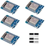
- This is D1 mini, it is a mini NodeMcu Lua WiFi board based on ESP-8266EX.
- 11 digital input / output pins, all pins with interrupt / PWM / I2C / support 1 line (except D0); 1 analog input(3.2V max input). Micro USB connection; Compatible with Arduino; 1MB Flash; 500mA resettable fuse.
- WIFI development board,4M bytes.5V 1A switching power supply (switching power supply)onboard.
- Our D1 mini development board compatible with Arduino WeMos and can be programmed in the compatible for Arduino IDE.
- ESP8266 ESP-12 ESP-12F NodeMcu Mini D1 Module WeMos Lua 4M Bytes WLAN WiFi Internet Development Board Base on ESP8266 ESP-12F
| Limitation | Practical effect | What to try |
|---|---|---|
| 2.4 GHz only | More interference from neighboring routers, Bluetooth devices, and microwaves | Use WiFi channels 1, 6, or 11 and test which is least congested |
| Single radio | Lower throughput because traffic is repeated on the same channel | Use it for low-bandwidth devices rather than high-speed clients |
| Limited RAM and CPU | Crashes or slow response with too many connected devices | Keep the client count small, ideally under five active devices |
| Small antenna | Weak range improvement if the board is poorly placed | Place it midway between router and target area, away from metal and walls |
Placement matters as much as firmware. The ESP8266 should not be installed where the original WiFi is already unusable; it needs a stable connection to repeat. A good starting point is halfway between the router and the dead zone, then move it closer to the router if the uplink is unstable. Keep the board elevated, clear of power bricks, metal enclosures, thick concrete, and appliances. If the module has an external antenna connector, use a matched 2.4 GHz antenna rather than a random wire unless the board is designed for that modification.
Quick wins for a faster PC:
Repair Windows errors before they cause bigger problemsFix Now →Fix the driver behind crashes, sound loss and screen glitchesFind Drivers →Security and compatibility also deserve attention. Use WPA2-Personal where possible, avoid open repeated networks, and change any default admin password in repeater firmware. Some captive portals, enterprise WPA networks, guest networks with client isolation, and routers with strict MAC filtering may not work cleanly through a simple ESP8266 NAT repeater. If you need reliable whole-home coverage, seamless roaming, high throughput, or support for many users, a purpose-built mesh system, wired access point, or powerline access point will be far more dependable.
Frequently Asked Questions
Can an ESP8266 really work as a WiFi range extender?
Yes, an ESP8266 can act as a basic WiFi repeater by connecting to your main router as a station and creating its own access point for nearby devices. It is useful for low-bandwidth devices such as sensors, smart plugs, cameras with modest data needs, or MQTT clients. It is not a replacement for a proper mesh system or commercial dual-band extender because the ESP8266 has limited processing power, RAM, and only one 2.4 GHz radio.
Should I use Arduino code or dedicated ESP8266 repeater firmware?
If you want a simple, working repeater, dedicated ESP8266 repeater firmware is usually the easier option because it already includes NAT, access point setup, and a web configuration interface. Arduino code is better if you want to combine repeating with your own project features, such as sensors, relays, or custom captive portal behavior. For most beginners, flashing a proven repeater firmware is faster and more reliable than building the full networking behavior from scratch.
Why is the internet speed much slower through the ESP8266 repeater?
The ESP8266 uses a single 2.4 GHz radio, so it has to receive data from the router and retransmit it to clients on the same radio channel. This usually cuts throughput significantly, and real-world speeds may be only a few Mbps or less depending on signal strength, interference, and firmware settings. For web browsing, IoT devices, and small data transfers it can be acceptable, but it is not suitable for HD streaming, gaming, or large downloads.
Do these 3 things before closing this tab:
1Scan for outdated or missing drivers - takes under a minute2Clear out junk files and repair common Windows errors3Fix the driver behind crashes, sound loss and screen glitchesWhat power supply should I use for a stable ESP8266 WiFi extender?
Use a reliable 5 V USB power supply for NodeMCU or Wemos D1 mini boards, preferably rated for at least 1 A. If you are using a bare ESP-12 module, provide a stable 3.3 V regulator that can handle current spikes of 300 mA or more. Weak USB ports, long cables, and poor regulators can cause random resets, dropped connections, or failure to connect to the router.
What should I check if devices connect to the ESP8266 but have no internet?
First confirm that the ESP8266 itself is connected to your main router and that the router password, SSID, and security mode are correct. Make sure the firmware or sketch supports NAT routing, because a normal ESP8266 access point alone will not automatically share internet access. Also check that the repeated network uses a compatible 2.4 GHz setup, since the ESP8266 does not support 5 GHz WiFi.
Bottom Line
An ESP8266 can make a useful low-cost WiFi repeater for light-duty coverage gaps, especially for sensors, smart plugs, or occasional browsing. With the right board, stable power, suitable repeater firmware, and careful placement between your router and the weak-signal area, setup is straightforward in the Arduino-friendly ecosystem.
Keep expectations realistic: the ESP8266 has limited throughput, single-radio repeating reduces speed, and placement matters more than raw settings. If you need reliable high-speed coverage for phones, laptops, or streaming, use this project as a learning tool or temporary fix and consider a dedicated mesh node or access point as the next step.
What’s actually slowing this PC down?
Pick the symptom - the matching free tool is one click away.
Quick Recap
Product prices and availability are accurate as of the date/time indicated and are subject to change. Any price and availability information displayed on Amazon at the time of purchase will apply.




