Recommended Free Tools
The WEMOS/Lolin ESP32 board with an integrated OLED display is a compact development board that combines Wi-Fi, Bluetooth, GPIO pins, and a small screen on one module. It is a convenient choice for sensor dashboards, network status displays, portable gadgets, and quick ESP32 experiments where you want visual feedback without adding a separate display module.
Getting started is mostly a matter of preparing the Arduino IDE, installing the ESP32 board package, adding the right OLED display libraries, and using the correct I2C settings for the built-in screen. Once those pieces are in place, you can upload a simple test sketch and confirm that the board, USB driver, and display are all working together.
Board Overview and Built-In OLED Specifications
The WEMOS/Lolin ESP32 boards with an integrated OLED combine a full ESP32 development board and a small monochrome display on the same PCB. For beginners, this is convenient because you can print sensor readings, Wi-Fi status, IP addresses, menu text, or debug messages without adding a separate display module. Most versions are based on the ESP32-WROOM module, giving you Wi-Fi, Bluetooth, plenty of GPIO pins, and enough memory for typical Arduino projects.
The exact layout depends on the board revision, but the common format includes a USB connector for programming and power, a reset button, a boot or flash button, pin headers along both sides, and a 0.96-inch OLED display mounted near one end of the board. The display is usually a 128×64 pixel monochrome OLED driven by an SSD1306-compatible controller. It communicates over I2C, which means it uses only two signal lines: SDA for data and SCL for clock.
Do these 3 things before closing this tab:
1Fix the driver behind crashes, sound loss and screen glitches2Repair Windows errors before they cause bigger problems3Scan for outdated or missing drivers - takes under a minute#1 Best Overall

- The ESP32 0.96'' OLED board has all the features of the traditional ESP32 Devkit V1 module,with the same exact peripheral ports,offers seamless integration with a 0.96-inch OLED display, eliminating the need for frustrating wires and breadboards.Display features a high-resolution 128x64 with SSD1306 driver and is compatible with I2C interfaces. Plus,It uses Micro usb cable to connect. Say goodbye to messy setups and hello to hassle-free electronics with the ESP32 board
- The Board is based on ESP32-WROOM-32 module integrated with Antenna switches, RF Balun, power amplifiers, low-noise amplifiers, filters, and management modules, and the entire solution occupies the least area of PCB. 2.4 GHz Wi-Fi plus BLE dual-mode chip, with TSMC Ultra-low power consumption 40nm technology, power dissipation performance and RF performance is the best, safe and reliable, easy to extend to a variety of applications
- This board uses I2C to connect to an OLED display via the SDA (D21 / GPIO21) and SCL (D22 / GPIO22) pins. With this board,it's easy to display a variety of information and data
- To install the new version driver for CH340,simply search for the keywords "CH340 Driver" on Google.com or Bing.com and follow the installation instructions provided.Recommended for Win10 Operating System
- This board is an outstanding option for various Internet of Things (IoT) projects. It can be used to display network connection status,monitor information, power levels, and other relevant data. Additionally, it's suitable for building Internet Weather Stations, News Stations, Clocks, and Other similar applications
Typical board features
- Microcontroller: ESP32, commonly the ESP32-WROOM-32 module.
- Wireless: 2.4 GHz Wi-Fi and Bluetooth/Bluetooth LE support.
- Programming interface: USB-to-serial converter, often CH340, CP210x, or similar depending on the clone or revision.
- Operating voltage: 3.3 V logic for ESP32 GPIO pins.
- USB power: Usually powered from 5 V over USB, regulated down to 3.3 V on the board.
- Display: Integrated 0.96-inch OLED, commonly 128×64 pixels, monochrome.
- Display controller: Usually SSD1306-compatible.
- Display interface: I2C, typically using a fixed address such as 0x3C.
Many WEMOS/Lolin-style ESP32 OLED boards connect the built-in display to GPIO 5 for SDA and GPIO 4 for SCL, but this is not universal. Some boards use GPIO 21 and GPIO 22, matching the more common default ESP32 I2C pins. Others may label the pins directly on the silkscreen as SDA and SCL. Before using an example sketch, check the product page, board printing, or schematic for your specific model. If the display stays blank while the upload succeeds, the I2C pins or address are the first settings to verify.
| OLED setting | Common value | What to check |
|---|---|---|
| Resolution | 128×64 | Some compact displays may be 128×32, though this is less common on these boards. |
| I2C address | 0x3C | A few modules use 0x3D; an I2C scanner can confirm it. |
| SDA pin | GPIO 5 or GPIO 21 | Depends on board revision and manufacturer. |
| SCL pin | GPIO 4 or GPIO 22 | Must match the pin used in the sketch. |
| Driver library | SSD1306 | Adafruit SSD1306 and U8g2 are both popular options. |
Because the ESP32 uses 3.3 V , avoid connecting 5 V signals directly to its GPIO pins. The integrated OLED is already wired correctly on the board, so no external wiring is needed for the first display test. The only connection required to get started is a USB cable between the board and your computer. Once the board package, serial driver, and OLED library are installed, you can upload a sketch that initializes the correct I2C pins and writes text to the built-in display.
Required Tools, Drivers, and Arduino IDE Setup
Before programming a WEMOS/Lolin ESP32 board with an integrated OLED, gather a few basic items and prepare your computer for ESP32 development. The board is usually powered and programmed through USB, so most setup problems come down to the USB cable, the USB-to-serial driver, or an incomplete Arduino IDE configuration. Starting with these pieces in place makes the first OLED test sketch much easier.
Tools and hardware you need
- WEMOS/Lolin ESP32 board with built-in OLED: Common variants include boards labeled WEMOS, LOLIN, TTGO, or ESP32 OLED. The exact layout may differ, but the setup process is similar.
- USB data cable: Use a known-good USB cable that supports data, not a charge-only cable. Many upload failures are caused by power-only cables.
- Computer: Windows, macOS, or Linux can be used with the Arduino IDE.
- Arduino IDE: Arduino IDE 2.x is recommended for new users because it includes a modern board manager, library manager, serial monitor, and clearer upload messages.
- Internet connection: Needed to download the ESP32 board package and OLED display libraries.
Most WEMOS/Lolin ESP32 boards include a USB-to-serial chip that allows the computer to upload sketches to the ESP32. Depending on the board revision, this chip is commonly a CP210x, CH340/CH341, or sometimes an FTDI interface. If your computer does not recognize the board when it is plugged in, installing the correct driver is the first thing to check.
| USB-to-serial chip | Common driver name | Typical boards |
|---|---|---|
| CP2102 / CP2104 | Silicon Labs CP210x driver | Many WEMOS/Lolin ESP32 OLED boards |
| CH340 / CH341 | WCH CH340 driver | Many low-cost ESP32 development boards |
| FT232 | FTDI VCP driver | Less common ESP32 variants |
On Windows, open Device Manager after plugging in the board. A correctly detected board usually appears under Ports (COM & LPT) as a COM port. If it appears as an unknown device, install the driver for the USB-to-serial chip on your board. On macOS, the port normally appears in the Arduino IDE as something like /dev/cu.SLAB_USBtoUART, /dev/cu.wchusbserial, or /dev/cu.usbserial. On Linux, the port is commonly /dev/ttyUSB0 or /dev/ttyACM0; you may need to add your user account to the dialout group before uploads will work.
After the driver is handled, install and open the Arduino IDE. In Arduino IDE 2.x, go to File > Preferences and make sure the editor is ready for board package installation. The actual ESP32 platform support is added in the next step using the Boards Manager, but this is a good time to confirm that the IDE launches correctly, the USB port appears when the board is connected, and the serial monitor can be opened. If the port appears and disappears as you unplug and reconnect the board, the computer is communicating with the USB interface properly.
For a smoother first upload, connect the ESP32 board directly to the computer rather than through an unpowered USB hub. Avoid connecting external modules or sensors while setting up the IDE, since the built-in OLED is already wired to the ESP32 on the board. Once the Arduino IDE can see the board’s serial port, you are ready to install ESP32 board support and the OLED libraries needed for the display example.
Installing ESP32 Board Support and OLED Libraries
After the USB driver and Arduino IDE are ready, the next step is to add ESP32 support and install the OLED display libraries. The Arduino IDE does not include ESP32 boards by default, so you need to add Espressif’s board package before the WEMOS/Lolin ESP32 board will appear in the board list. The integrated OLED also needs a graphics library that can talk to the small SSD1306-style display over I2C.
Adding the ESP32 board package URL
Open the Arduino IDE and go to File > Preferences. In the field named Additional Boards Manager URLs, add the Espressif ESP32 package URL:
Rank #2

- 3PCS ESP32-C3 OLED Development Board With 0.42 Inch OLED Module Ceramic Antenna Wifi Bluetooth ESP32 Supermini Development Board
- ESP32C3 0LED development board based on ESP32C3FN4/FH4 design and production of core board, built-in 4M flash, with WiFi and Bluetooth two modes, onboard ceramic antenna, equipped with 0.42 inch 0LED screen, support for usb download, invested heavily in the launch of gold ESP32C3 0LED development board
- High cost-effectiveness, compared to the performance and functionality it provides, ESP32-C3 has significant cost-effectiveness and is suitable for large-scale deployment of IoT projects.
- Rich peripheral interfaces with abundant peripherals and functions, suitable for small projects and scenarios such as IoT, wearable devices, and smart homes
- Pin interfaces: 1xI2C, 1xSPI, 2xUART, 11xGPIO (PWM), 4xADC
https://espressif.github.io/arduino-esp32/package_esp32_index.json
If there is already another URL in this box, click the small icon at the right side of the field and place each URL on its own line. After saving the preferences, go to Tools > Board > Boards Manager. Search for esp32, find the package named esp32 by Espressif Systems, and install it. For a beginner setup, the latest stable version is usually the best choice unless a project specifically asks for an older release.
Installing OLED display libraries
Most WEMOS/Lolin ESP32 boards with an integrated OLED use a small monochrome display based on the SSD1306 controller. The display is normally connected internally using I2C, so you do not need to wire the screen yourself. You only need the correct library and the correct I2C pin settings in your sketch.
What’s actually slowing this PC down?
Pick the symptom - the matching free tool is one click away.
In the Arduino IDE, open Tools > Manage Libraries or Sketch > Include Library > Manage Libraries. Search for and install the following libraries:
- Adafruit SSD1306 by Adafruit: controls SSD1306 OLED displays.
- Adafruit GFX Library by Adafruit: provides drawing functions such as text, lines, rectangles, and pixels.
The Arduino Library Manager may prompt you to install dependencies when installing Adafruit SSD1306. Accept the prompt so that Adafruit GFX and any required helper libraries are installed automatically. This combination is widely used, well documented, and works well for a first test sketch on integrated OLED ESP32 boards.
Common built-in OLED settings
Although the OLED is physically attached to the ESP32 board, its configuration can vary slightly between board revisions. The most common setup is a 128 × 64 pixel display at I2C address 0x3C. Some smaller boards may use 128 × 32, and a few displays may respond at 0x3D. If your first test uploads successfully but the display stays blank, the screen size, I2C address, or SDA/SCL pin values are the first settings to check.
| Setting | Common Value | What It Means |
|---|---|---|
| Display controller | SSD1306 | OLED driver chip used by many integrated displays |
| Resolution | 128 × 64 | Pixel width and height used in the display constructor |
| I2C address | 0x3C | Address used by the ESP32 to communicate with the OLED |
| Interface | I2C | Two-wire communication bus using SDA and SCL pins |
Once the ESP32 board package and OLED libraries are installed, restart the Arduino IDE if the new board options do not appear immediately. You should now be able to select an ESP32 board profile, choose the correct USB port, include the OLED libraries in a sketch, and move on to uploading the first display test.
Quick wins for a faster PC:
Repair Windows errors before they cause bigger problemsFix Now →Scan for outdated or missing drivers - takes under a minuteDriver Scan →Clear out junk files and repair common Windows errorsFree Scan →Selecting the Correct Board, Port, and OLED I2C Settings
After installing the ESP32 board package and OLED libraries, the next step is to make sure the Arduino IDE is talking to the right hardware. WEMOS/Lolin ESP32 boards with a built-in OLED are usually programmed like a standard ESP32 development board, but the exact menu choice can vary depending on the model and the board package version. Choosing a compatible board profile, the correct USB serial port, and the right I2C display settings prevents the most common beginner problems: failed uploads, blank screens, and sketches that compile but do nothing visible.
Choosing the board in Arduino IDE
Open Tools > Board and select an ESP32 profile that matches your board as closely as possible. For many WEMOS/Lolin ESP32 OLED boards, LOLIN D32, WEMOS LOLIN32, or a similar Lolin ESP32 option may appear if your ESP32 board package includes it. If you do not see a model-specific entry, ESP32 Dev Module is usually a safe starting point for basic sketches and OLED tests.
Rank #3
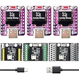
- 【TRIPLE ESP32-C3 BOARDS WITH OLED DISPLAYS】Includes 3 compact ESP32-C3 development boards with integrated OLED screens for data readout and Wi-Fi/Bluetooth LE connectivity — for IoT prototyping and real-time monitoring.
- 【LIPO UPS POWER MANAGEMENT】LiPo batteries (not included) act as instant backup: Type-C powers the board and charges the battery when connected, switching to battery power without reboots or interruptions for continuous operation.
- 【VERSATILE EXPANSION SHIELDS】Comes with a 2.54mm Expansion Shield (dual male/female GPIO pins), a Screw Terminal Shield for permanent projects, and a Non-Screw Terminal Shield for fast prototyping with direct cable connections.
- 【UNIVERSAL LIPO BATTERY COMPATIBILITY】All shields support protected LiPo batteries (e.g., 18650), with automatic 3.3V step-down for the ESP32-C3 and charging via USB Type-C for uninterrupted operation.
- 【BATTERY MONITORING MADE SIMPLE】Integrated battery monitor pads on every shield — short them to enable voltage tracking on your ESP32-C3 for power management in portable setups.
- Board: Use a Lolin/WEMOS ESP32 option if available; otherwise try ESP32 Dev Module.
- Upload Speed: Start with 115200 for reliability. Higher speeds may work, but can make troubleshooting harder.
- CPU Frequency: 240 MHz is typical for ESP32 boards.
- Flash Frequency: 40 MHz is a conservative default.
- Partition Scheme: The default option is fine for a first OLED example.
Selecting the serial port
Connect the board with a USB cable that supports data, not just charging. In the Arduino IDE, go to Tools > Port and select the port that appears when the board is plugged in. On Windows, it often looks like COM3, COM4, or another numbered COM port. On macOS, it may appear as /dev/cu.SLAB_USBtoUART, /dev/cu.usbserial-…, or /dev/cu.wchusbserial…. On Linux, it is commonly /dev/ttyUSB0 or /dev/ttyACM0.
If several ports are listed, unplug the board, open the Port menu, the available entries, then plug the board back in and check again. The newly appearing entry is usually the ESP32. If no new port appears, the USB cable, USB driver, or USB connector is the first place to check. Many WEMOS/Lolin-style boards use either a CP210x or CH340 USB-to-serial chip, so the port name may reflect one of those drivers.
Confirming the OLED I2C settings
The integrated OLED on these boards is normally connected over I2C, so there is no separate display wiring to add. However, the sketch must use the correct I2C address and pins. Most built-in OLED versions use address 0x3C, while some displays use 0x3D. The common display size is 128×64 pixels, although a few compact boards may use a smaller 128×32 panel.
| Setting | Common value | What to check |
|---|---|---|
| OLED interface | I2C | Built-in display usually shares the ESP32 I2C bus |
| I2C address | 0x3C | Try 0x3D if the screen stays blank |
| Resolution | 128×64 | Match this in the display library constructor |
| SDA / SCL pins | Board-dependent | Common examples include GPIO 5 / GPIO 4 or GPIO 21 / GPIO 22 |
Before uploading the first OLED sketch, check the pin labels printed on the board or the vendor pinout page for your exact WEMOS/Lolin model. Some integrated OLED boards route the display to non-default ESP32 I2C pins, so a sketch written for a generic ESP32 may compile correctly but show a blank display. If the example code includes a line such as Wire.begin(SDA, SCL), update those two values to match your board’s OLED SDA and SCL pins.
Uploading a First OLED Display Test Sketch
With the ESP32 board package installed, the USB driver working, and the OLED library available, you can upload a small test sketch to confirm that both the microcontroller and the built-in display are responding correctly. Most WEMOS/Lolin ESP32 boards with an integrated OLED use an SSD1306-compatible 128×64 display connected over I2C. Common pin assignments are SDA on GPIO 5 and SCL on GPIO 4, although some variants may differ, so use the pins that match your board documentation or silkscreen.
Open the Arduino IDE and create a new sketch. The example below uses the widely used Adafruit SSD1306 and Adafruit GFX libraries. It initializes the OLED, clears the screen, prints a few lines of text, and draws a simple rectangle so you can verify text and graphics output in one upload.
#include <Wire.h>

#include <Adafruit_GFX.h>

#include <Adafruit_SSD1306.h>
#define SCREEN_WIDTH 128
#define SCREEN_HEIGHT 64
#define OLED_SDA 5
#define OLED_SCL 4
#define OLED_RESET -1
#define OLED_ADDRESS 0x3C
Adafruit_SSD1306 display(SCREEN_WIDTH, SCREEN_HEIGHT, &Wire, OLED_RESET);
void setup() {
Serial.begin(115200);
delay(1000);
Wire.begin(OLED_SDA, OLED_SCL);
if (!display.begin(SSD1306_SWITCHCAPVCC, OLED_ADDRESS)) {
Serial.println("OLED not found");
while (true) {
delay(100);
}
}
Free tools Windows power users keep installed
One-click scans. No signup required.
Rank #4

- The WeMos d1 mini ESP32 Pro development board, everything needed to program the latest ESP32 module (the ESP-WROOM-32), ESP32/32S WIFI Development Bluetooth ESP8266 Module CP2104 for Arduino
- Different than ESP8266 Mini V2 and ESP8266 D1 Pro, the ESP32 D1 carries the ESP32-WROOM-32 module while keeping the same form factor
- The DOIT esp32 devkit is a single chip solution that combines Bluetooth and 2.4 GHz Wi-Fi capabilities
- The WeMos mini d1 family of boards is one of the latest additions to the ESP32- and ESP8266-based Internet Of Things (IoT) ecosystem
- Together with a growing set of expansion boards (shields), the WeMos family is a great solution for building projects quickly using both the ESP8266 and ESP32 SoC
display.clearDisplay();
display.setTextSize(1);
display.setTextColor(SSD1306_WHITE);
display.setCursor(0, 0);
display.println("ESP32 OLED Test");
display.println("WEMOS / Lolin");
display.println();
display.setTextSize(2);
display.println("Hello!");
display.drawRect(0, 48, 128, 16, SSD1306_WHITE);
display.setTextSize(1);
display.setCursor(8, 52);
display.println("Display working");
display.display();
}
void loop() {
}
Before uploading, check that the selected board and port are still correct in the Arduino IDE. For many integrated OLED ESP32 boards, selecting LOLIN D32, WEMOS LOLIN32, or a generic ESP32 Dev Module works, depending on the exact board package and hardware revision. Set the upload speed to a conservative value such as 115200 or 460800 if you have upload problems at higher speeds.
The Tool Desk
Outbyte PC Repair FREERepair Windows errors before they cause bigger problemsFix Now →Outbyte Driver Updater FREEFix the driver behind crashes, sound loss and screen glitchesFind Drivers →- Connect the ESP32 board to your computer with a USB data cable.
- Choose the correct ESP32 board from the Arduino IDE board menu.
- Select the matching serial port from the port menu.
- Paste the sketch into the editor and click Upload.
- If prompted by the upload process, hold the BOOT button until writing begins, then release it.
After the upload finishes, the board should restart automatically and the OLED should show the test message. If the upload succeeds but the screen remains blank, first try changing OLED_ADDRESS from 0x3C to 0x3D. If that does not help, confirm the I2C pins used in Wire.begin(OLED_SDA, OLED_SCL). A blank display with a working serial monitor usually points to an address or pin mismatch rather than a failed upload.
Once this sketch works, you have a reliable baseline for future projects. Keep a copy of it so you can quickly test the board after changing libraries, Arduino IDE versions, or USB cables. From here, you can replace the static text with sensor readings, Wi-Fi status, battery voltage, menu screens, or debugging messages for your ESP32 project.
Independent reader supportYour contribution helps us test, update, and keep practical guides available for everyone.Troubleshooting Upload, Driver, and Display Issues
Most problems with a WEMOS/Lolin ESP32 board and integrated OLED fall into three areas: the computer cannot see the board, the sketch will not upload, or the OLED stays blank after a successful upload. Work through the checks in order, because a USB or board-selection problem can look like a display problem when the sketch never actually reaches the ESP32.
Board not detected by the computer
If no serial port appears in the Arduino IDE, start with the USB connection. Many Micro-USB cables are charge-only and do not include data wires, so try a known data cable before changing software settings. Also plug the board directly into the computer rather than through an unpowered USB hub. On Windows, open Device Manager and check whether a new COM port appears when you connect the board. On macOS or Linux, look for a new device such as /dev/cu.usbserial, /dev/cu.SLAB_USBtoUART, or /dev/ttyUSB0.
PC Slower Than It Used to Be?
A free scan shows the junk files, broken settings and background clutter dragging Windows down - then fixes them in one click.Free scan · Windows 10 & 11Outdated Drivers Are Slowing You Down
One free scan finds every outdated or missing driver and matches the right update for your exact hardware.Free scan · exact hardware match- CH340/CH9102 USB chip: Install the WCH driver if the board does not appear automatically.
- CP210x USB chip: Install the Silicon Labs CP210x driver if the port is missing.
- Permission issue on Linux: Add your user to the dialout group, then log out and back in.
- Unstable connection: Try another USB port, shorter cable, or a powered hub.
Upload fails or gets stuck connecting
If the Arduino IDE shows messages such as Failed to connect to ESP32, Timed out waiting for packet header, or endless dots while connecting, the ESP32 may not be entering bootloader mode. Many WEMOS/Lolin ESP32 boards auto-reset correctly, but some need manual help. Hold the BOOT button, click Upload, and release BOOT when the IDE changes from compiling to connecting or uploading. If the board has an EN or RST button, pressing it once after upload can restart the sketch.
Also confirm that the selected board profile matches the module closely enough. For many integrated OLED ESP32 boards, WEMOS LOLIN32, LOLIN D32, or a generic ESP32 Dev Module profile will work, but flash size and upload speed can affect reliability. If uploads fail at high speed, reduce Upload Speed to 115200 or 460800. Disconnect external hardware while testing, especially anything connected to GPIO0, GPIO2, GPIO12, or GPIO15, because strapping pins can interfere with boot mode.
Best Value

- This product adopts ESP32-S3R8 chip with 2.4GHz WiFi and Bluetooth BLE 5 support, integrates high-capacity Flash and PSRAM. Onboard 1.43inch AMOLED display which can smoothly run GUI programs such as LVGL.
- Onboard rich peripheral resources such as RTC chip, QMI8658 6-axis IMU, TF card slot, Lithium battery header, etc., and reserved USB, UART, I2C and GPIO pin headers, offering strong compatibility and expandability. It is suitable for the quick development of the HMI and other ESP32-S3 applications.
- Equipped with high-performance Xtensa 32-bit LX7 dual-core processor, up to 240MHz main frequency Supports 2.4GHz Wi-Fi (802.11 b/g/n) and Bluetooth 5 (LE), with an onboard antenna. Supports switching to use external antenna via resoldering an onboard resistor Built-in 512KB SRAM and 384KB ROM, with onboard 16MB Flash and 8MB PSRAM
- Onboard 1.43inch AMOLED display, QSPI interface, 466 × 466 resolution, 16.7M color Supports capacitive touch function controlled via I2C interface, with interrupt support Onboard QMI8658 6-axis IMU (3-axis accelerometer and 3-axis gyroscope) for detecting motion gestures, counting steps, etc.
- Onboard PCF85063 RTC chip with reserved SH1.0 RTC battery header (supports charging) for RTC function requirement Onboard RST button and programmable BOOT button for easy custom function development Onboard 3.7V MX1.25 Lithium battery recharge/discharge header Onboard TF card slot for external TF card storage of pictures or files
OLED remains blank after upload
A blank OLED does not always mean the display is defective. First verify that the sketch is running by adding serial output or blinking the onboard LED if available. Then check the OLED library settings. Most integrated displays on these boards are small monochrome SSD1306 panels, commonly 128×64 pixels, using I2C address 0x3C. Some variants use 0x3D or a different controller, so run an I2C scanner sketch if the display does not respond.
| Symptom | Common cause | Fix |
|---|---|---|
| Upload succeeds, OLED blank | Wrong I2C address | Try 0x3C, then 0x3D, or run an I2C scanner |
| Display shows random pixels | Wrong resolution or driver | Select SSD1306 128×64 unless your board documentation says otherwise |
| Compilation error for display library | Missing dependency | Install Adafruit GFX with Adafruit SSD1306, or the matching U8g2 library |
| Only serial monitor works | Wrong SDA/SCL pins in sketch | Use the board’s built-in OLED I2C pins, often GPIO5 and GPIO4 on common Lolin OLED variants |
If the OLED still does not initialize, check whether your sketch calls Wire.begin(SDA, SCL) with the correct pins for that exact board version. Integrated OLED models are not all wired the same, even when they look similar. Lowering the I2C clock speed can also help with marginal boards; use a standard 100 kHz setting while testing. Once the display responds, you can restore faster settings and continue building your project.
Frequently Asked Questions
Which board should I select in the Arduino IDE for a WEMOS/Lolin ESP32 with built-in OLED?
For most WEMOS/Lolin ESP32 OLED boards, selecting “WEMOS LOLIN32” or “LOLIN D32” works, depending on the exact board package version installed. If uploads fail or the pin mapping seems wrong, try “ESP32 Dev Module” with the correct flash settings. Always confirm the USB port under Tools > Port before uploading.
What OLED library should I use with the built-in display?
The most common choice is the Adafruit SSD1306 library together with the Adafruit GFX library. Many integrated OLED boards use a 128×64 SSD1306 display over I2C, usually at address 0x3C. If the display stays blank, run an I2C scanner sketch to confirm the address.
Which I2C pins does the built-in OLED use on the ESP32 board?
Many WEMOS/Lolin ESP32 boards with integrated OLED displays use GPIO 5 for SCL and GPIO 4 for SDA, but this can vary by board revision. Some examples use Wire.begin(5, 4), while others require different pin assignments. Check the board silkscreen, product page, or schematic if the display does not respond.
Why does the sketch upload fail even though the board is connected?
Upload issues are often caused by a missing USB-to-serial driver, the wrong COM port, a bad USB cable, or the board not entering bootloader mode. Make sure the cable supports data, install the CP210x or CH340 driver if needed, and select the correct port in the Arduino IDE. If uploading still fails, hold the BOOT button while the IDE shows “Connecting,” then release it after the upload starts.
The Tool Desk
Outbyte Driver Updater FREEScan for outdated or missing drivers - takes under a minuteDriver Scan →Outbyte PC Repair FREEClear out junk files and repair common Windows errorsFree Scan →Why is the OLED screen blank after uploading the example sketch?
A blank OLED usually means the sketch is using the wrong I2C address, wrong SDA/SCL pins, or wrong display size. Confirm whether your display is 128×64 or 128×32 and use the matching initialization settings. Also check that the code calls display.begin(), display.clearDisplay(), display.display(), and uses a visible text color such as SSD1306_WHITE.
Bottom Line
A WEMOS/Lolin ESP32 with an integrated OLED is a compact, beginner-friendly board that lets you move quickly from setup to a working display project. Once the Arduino IDE is configured, the correct ESP32 board package is installed, and the OLED libraries are added, you can test the screen with a simple sketch and confirm the I2C address and pin settings.
Your next step is to build on the first OLED example by showing sensor readings, Wi-Fi status, menu screens, or project alerts directly on the display. Keep the board pinout, OLED address, and library settings handy so future troubleshooting is quick and straightforward.
Quick Recap
Product prices and availability are accurate as of the date/time indicated and are subject to change. Any price and availability information displayed on Amazon at the time of purchase will apply.
Free tools Windows power users keep installed
One-click scans. No signup required.




