Verdict: Tube Lab is an educational, single-ended amplifier experiment built around a 12AX7 dual triode, an approximately 170 V DC supply and an improvised automotive ignition-coil output transformer. It demonstrates tube gain, rectification, transformer action and impedance matching, but its high voltage and non-isolated speaker output make the original circuit unsuitable for casual beginners, headphones or an exposed breadboard build.
The project is described in the All About Circuits vacuum-tube amplifier experiment. Treat the source circuit as a historical teaching demonstration. A responsible modern build needs an enclosed chassis, fusing, rated test equipment and a purpose-built isolated audio output transformer.

As an Amazon Associate I earn from qualifying purchases.
What Tube Lab actually builds
The circuit is a very low-power, single-ended tube amplifier. The source describes an expected output of less than 1 W into a nominal 8 Ω speaker; that is an attributed design claim, not an independent performance measurement. Its purpose is to show how a thermionic triode can amplify a small audio signal, not to provide hi-fi sound, guitar-amplifier power or a dependable consumer product.
The principal device is one 12AX7/ECC83 dual triode. Each envelope contains two triode sections. The experiment can use one section for a simpler demonstration or connect corresponding plates, grids and cathodes in parallel to increase available current and output capability. The source lists a 12AX7 plate-voltage maximum of 330 V, but that absolute rating says nothing about whether a circuit is safe to touch; the project’s approximately 170 V supply remains a potentially lethal shock source.
#1 Best Overall

- Great tone
- Reliable tubes
- Power tubes are matched
The page appears in the site’s “Discrete Semiconductor Circuit Projects” taxonomy, available from the Electronics Textbook experiment index, even though the amplifier itself is a vacuum-tube circuit. The rectifier is the semiconductor part.
Safety comes before the parts list
Do not copy the original wiring as a beginner project. The filter capacitor can retain dangerous energy after shutdown, and the automotive ignition coil used at the output is generally an autotransformer rather than an isolated transformer. That means the speaker terminals can sit at hazardous DC potential relative to circuit ground.
- Never connect headphones.
- Do not touch the speaker terminals, output wiring or exposed tube circuitry while powered.
- Do not assume transformer isolation makes the amplifier touch-safe. It reduces some mains-related risks but does not remove the high-voltage hazard or isolate the speaker output.
- Use a proper socket and enclosed chassis, not an exposed solderless breadboard, for any serious construction.
- Fit a mains-rated fuse, switch and strain relief; use touch-safe terminal blocks and clearly segregate low-voltage input wiring from B+ wiring.
- Use a CAT-rated meter and insulated probes. During energized measurements, keep one hand away from the circuit and avoid any oscilloscope ground connection that could short a live node to earth.
- Disconnect power before changing wiring. Treat every capacitor as charged until its voltage has been measured.
The original instructions call for waiting until the supply falls below 30 V before touching the circuit. That threshold must be verified with a suitably rated meter; a countdown is not a substitute for measurement.
Free tools Windows power users keep installed
One-click scans. No signup required.
How the circuit is arranged
Audio path
- A battery-powered radio, CD player, keyboard or other low-level source feeds the input.
- A 0.1 µF coupling capacitor passes the changing audio voltage while blocking source DC.
- A 100 kΩ resistor establishes the tube grid’s DC reference.
- The 12AX7 triode controls plate current as the grid signal changes.
- The plate drives an impedance-matching transformer.
- The transformer feeds the nominal 8 Ω loudspeaker.
The experiment keeps the bias arrangement deliberately simple. It is not a fully characterized modern tube amplifier with a carefully specified operating point, protection network or measured frequency response.
Rank #2

- New In Box Gain Matched Pair JJ Electronics Tesla 12AX7 ECC83-S Vacuum Tubes
- Size: 7.05 Ounce (Pack of 1)
Power path
- One transformer reduces 120 V AC to approximately 12 V AC.
- A second transformer is used in reverse, stepping that low voltage back up.
- A bridge rectifier converts the stepped-up AC to pulsating DC.
- An electrolytic reservoir capacitor filters the rectified waveform into approximately 170 V DC, commonly called B+.
- A bleeder resistor provides a discharge path when power is removed.
Using two transformers limits the current available if the plate-supply side is accidentally shorted and avoids directly rectifying household mains. This is a risk-reduction technique, not a guarantee of safe construction: the B+ node and stored capacitor energy are still hazardous.
Original parts and ratings
| Part | Original project detail | Modern construction note |
|---|---|---|
| Vacuum tube | One 12AX7 dual triode | Use a proper ceramic or quality noval socket; do not rely on loose wires soldered to tube pins. |
| Power transformers | Two 120 V AC-to-12 V AC transformers, with the second used in reverse | Confirm voltage, insulation, current rating and wiring before energizing. |
| Rectifier | Bridge rectifier module | Observe polarity and select voltage/current ratings with margin. |
| Filter capacitor | At least 47 µF, 200 VDC; 250 V is given as a preferred example | Use a reputable high-voltage electrolytic with suitable ripple-current, temperature and physical ratings. |
| Bleeder resistors | 100 kΩ resistors are listed | Verify voltage and power ratings; one RC time constant is not a safe-discharge guarantee. |
| Input capacitor | 0.1 µF, 250 WVDC | Keep its voltage rating appropriate to every node it could encounter. |
| Output device | Automotive ignition coil | Experimental and non-isolated; replace with a purpose-built isolated single-ended audio transformer in a safer redesign. |
| Load | 8 Ω speaker | Never substitute headphones or expose the speaker wiring. |
| Controls and source | SPST toggle switch and low-level audio source | Use a rated switch, fuse holder, enclosure and strain relief. |
The project notes that 12AX7 tubes are obtainable while suitable sockets may be harder to find. That is an argument for sourcing the socket first, not for omitting it.
Why an ignition coil is a questionable output transformer
A tube plate circuit operates at comparatively high voltage and low current, while an 8 Ω speaker needs a much lower voltage and higher current. A transformer changes that relationship. The source discusses an approximate 10,000:1 impedance ratio, corresponding to a turns ratio near 100:1, because impedance ratio follows the square of turns ratio. This is the project’s design rationale, not a guaranteed match for every ignition coil.
The Tool Desk
Outbyte Driver Updater FREEFix the driver behind crashes, sound loss and screen glitchesFind Drivers →Outbyte PC Repair FREEClear out junk files and repair common Windows errorsFree Scan →Several qualifications matter:
- Speaker impedance varies with frequency rather than remaining exactly 8 Ω.
- Effective tube output resistance depends on the operating point and circuit configuration.
- Automotive ignition coils are designed for short high-voltage ignition pulses, not broadband audio.
- Their frequency response, distortion, winding arrangement and power capability are poorly specified for this use.
- Many are autotransformers with a shared winding, so they do not provide galvanic isolation.
A purpose-built single-ended audio output transformer is the responsible replacement. Its primary impedance, secondary impedance, insulation system, frequency response and power rating should be chosen for the tube’s operating point and the speaker load. Electrical impedance matching and safe output isolation are separate requirements; the ignition coil may approximate the first while failing the second.
Rank #3
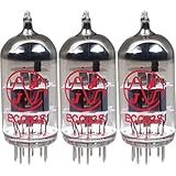
- This tube has a well balanced, colorful tone with strongly defined lows, mids and smooth highs
- It allows for more clean head-room than higher gain 12AX7s
- In overdrive, it is smooth and strong with well defined lows and mids
- When pushed into overdrive it offers clean distortion with well balanced lows and mids
- The JJ 12AX7 is well suited for all types of music and playing styles
Rectification, filtering and the bleeder resistor
The bridge rectifier turns the stepped-up AC into pulsating DC. The reservoir capacitor fills in the gaps between peaks, producing the approximate 170 V B+ rail used by the plate circuit. The capacitor must be rated above the actual voltage; the source’s 250 V example provides more margin than a 200 V minimum.
With 47 µF and 100 kΩ, the nominal time constant is:
τ = RC = 100,000 × 47 µF ≈ 4.7 seconds.
After one time constant, an initially charged capacitor is still at about 37% of its starting voltage. At 170 V that is roughly 63 V, which is not a safe-touch level. The bleeder improves discharge behavior but does not create a four-second safety timer. Measure the actual voltage and continue waiting until it is below the stated 30 V threshold, following a validated discharge procedure.
What’s actually slowing this PC down?
Pick the symptom - the matching free tool is one click away.
Series capacitors are not a drop-in substitute
Five 50 V capacitors in series can provide a higher aggregate voltage rating, but the total capacitance is approximately one-fifth that of one capacitor. Leakage differences can also make the voltage divide unevenly. Equal-value balancing resistors across the individual capacitors are needed to promote sharing, and each resistor must have appropriate voltage and power ratings.
Rank #4

- (3) T-12AX7-S-JJ
- (1) T-EL84-JJ-MP (Apex Matched), which includes:(2) T-EL84-JJ
What the 12AX7 is doing
Inside each triode, a heated cathode emits electrons toward the plate. A small voltage change at the grid controls the plate current, producing a larger voltage variation in the plate circuit. The heater requires its own low-voltage supply, while the plate requires the high-voltage B+ supply.
Paralleling the two triode sections connects their corresponding electrodes so they share the signal and load. That can increase available current compared with one section, but it does not turn the circuit into a high-power amplifier. Running one section is useful for a simpler classroom demonstration.
The input capacitor provides AC coupling, and the 100 kΩ resistor gives the grid a DC reference. This minimal arrangement is easy to follow educationally, but it omits the deliberate bias design, defined operating point, protection and characterization expected in a production amplifier.
Construction and first power-up
The source’s sequence is useful as a conceptual checklist, provided it is performed in an enclosed, current-limited and supervised setup rather than copied as exposed breadboard wiring.
- Build and verify the high-voltage supply separately before connecting the amplifier stage.
- With all power removed, inspect every connection and check continuity and resistance with an ohmmeter.
- Confirm capacitor polarity, transformer wiring, fuse placement, grounding and the isolation boundaries.
- Apply heater power only and verify the specified heater voltage. Allow approximately 30 seconds for the tube to warm.
- Set the audio source to minimum volume.
- Switch on the plate supply and measure the B+ output. The source expects approximately 170 V DC.
- Check that the tube’s filament sections show a soft orange glow. Glow alone does not prove correct pinout, bias or tube health.
- With a safe, isolated output arrangement and suitable speaker connected, raise the source level gradually.
- Switch off the plate supply before servicing. Discharge and measure the filter capacitor; do not touch the circuit until the voltage is verified below the chosen safe threshold.
Never leave an exposed or experimental high-voltage version unattended. A low audio wattage does not make the supply low risk.
Independent reader supportYour contribution helps us test, update, and keep practical guides available for everyone.Troubleshooting by symptom
No filament glow
- Open or defective tube filament.
- Incorrect 12AX7 pinout or poor socket contact.
- Missing, incorrect or overloaded heater supply.
- Defective transformer, switch, fuse or connection.
B+ absent or low
- Incorrect step-down or reverse step-up transformer wiring.
- Open switch, fuse or connection.
- Bridge rectifier installed with the wrong polarity.
- Shorted or incorrectly connected filter capacitor.
- Excessive load, unsuitable transformer ratings or a wiring short.
No audio
- Broken input connection or failed coupling capacitor.
- Incorrect tube wiring or missing grid reference.
- No plate supply or an incorrectly wired output transformer.
- Defective tube, speaker or audio source.
Weak or distorted audio
- Input driven too hard.
- Incorrect supply voltage or operating point.
- Poor impedance match.
- Ignition coil unsuitable for audio frequencies.
- Defective tube or speaker.
Loud 60 Hz hum
- Insufficient filtering.
- Poor grounding or a ground loop.
- Long, unshielded input wiring.
- Heater-to-signal coupling.
- Incorrect transformer wiring or a damaged output device.
Signal tracing can locate the missing stage: check the audio input, tube grid, tube plate, transformer connection and speaker in that order. An oscilloscope or voltmeter may be used only with correctly rated, safely grounded equipment. The source also describes a sensitive audio detector; coupling capacitors must block the circuit’s DC before any detector input.
How to measure without creating a new hazard
- Use a meter and leads rated for the voltage and expected transients; an unknown low-cost meter is not adequate evidence of safety.
- Do not clip an earth-referenced bench-scope ground to a node that can be above earth potential. Use an appropriate differential probe or an isolation strategy designed by someone competent with high-voltage measurement.
- Keep probes secured before energizing where possible, maintain clearances and use one-hand practice for live measurements.
- After shutdown, measure the capacitor directly and confirm that the voltage remains low after a short wait; a rising voltage can indicate dielectric absorption or an open bleeder.
What a safer redesign should change
A modern version should preserve the educational signal path while replacing the most hazardous assumptions.
- Install the 12AX7 in a proper socket inside a mechanically secure chassis.
- Use a purpose-built, galvanically isolated single-ended audio output transformer rather than an automotive ignition coil.
- Provide a mains-rated fuse, switch, strain relief, protective earth where applicable and touch-safe connectors.
- Use rated bleeder and discharge components, with a documented verification procedure.
- Separate input, heater, rectifier and B+ wiring physically; insulate or shield all high-voltage terminals.
- Use a high-voltage capacitor with suitable ripple, temperature and voltage margins.
- Label the B+ and output hazards and prevent access to speaker terminals that could be at hazardous potential.
For parts selection, recognized starting points include JJ Electronic for 12AX7 tubes (https://www.jj-electronic.com/), Antique Electronic Supply for sockets (https://www.tubesandmore.com/), Hammond Manufacturing for transformers and chassis (https://www.hammfg.com/), Mouser (https://www.mouser.com/) or DigiKey (https://www.digikey.com/) for rated capacitors, Vishay for resistors (https://www.vishay.com/) and Fluke for CAT-rated meters (https://www.fluke.com/). These are vendor starting points, not verified stock or price claims.
Useful extensions for experienced builders
- Compare one triode section with the paralleled configuration while keeping voltage and load ratings within limits.
- Measure hum, gain and frequency response with safe, isolated instrumentation rather than relying on subjective “tube sound” claims.
- Compare a purpose-built output transformer with the ignition-coil experiment and document distortion and bandwidth.
- Investigate a deliberate bias network or negative feedback only after the basic operating points and protection are established.
- Change B+ only within the voltage, dissipation and insulation limits of every component; the 330 V figure cited for the 12AX7 is an attributed maximum rating, not a target.
Who should build it?
| Reader | Recommendation |
|---|---|
| Electronics student or experienced hobbyist | Useful as a supervised demonstration of tubes, rectifiers, transformers and impedance matching, preferably with the safety redesign. |
| Absolute beginner or child | Do not build the original circuit; start with a low-voltage amplifier project and learn measurement safety first. |
| Anyone seeking hi-fi or guitar power | Choose a documented amplifier design with a specified operating point, isolated output transformer, enclosure and measured performance. |
| Headphone user | Never connect headphones to this topology. |
The Bottom Line
Tube Lab is valuable for learning how a 12AX7, rectifier, filter capacitor and transformer interact. It is not a safe, modern plug-and-play amplifier: the approximately 170 V B+ rail stores hazardous energy, and the ignition-coil autotransformer can leave the speaker output electrically dangerous. Preserve the experiment’s teaching goals, but use an enclosed chassis, rated protection and an isolated audio output transformer before treating it as a buildable amplifier.
Quick Recap
Product prices and availability are accurate as of the date/time indicated and are subject to change. Any price and availability information displayed on Amazon at the time of purchase will apply.

