What’s actually slowing this PC down?
Pick the symptom - the matching free tool is one click away.
There is no universal winner. Solid-state cooling (usually a thermoelectric or TEC module) actively pumps heat and can hold a small target at a controlled temperature with no moving parts. Fans reject heat by moving air through a heat sink. Heat pipes passively transport heat from a hot spot to a cooler sink, while vapor chambers spread that transport across a flat area. In every case, the heat ultimately has to leave the assembly.
The best choice depends on heat load, required temperature difference, available space, electrical power, noise, vibration, reliability and, above all, whether the hot side has a credible path to the surrounding environment. A TEC can be excellent for localized, quiet temperature control and a poor choice for bulk heat removal. A fan, heat pipe or vapor chamber can be highly effective in an electronics cooler, but none of them makes heat disappear.
As an Amazon Associate I earn from qualifying purchases.
What each cooling technology actually does
Thermoelectric (solid-state) cooling
A thermoelectric cooler uses the Peltier effect. When direct current passes through semiconductor couples, heat is absorbed at one face and released at the opposite face. Reversing current reverses the hot and cold sides, so the same device can provide heating or cooling. Because the process has no compressor, bearings or refrigerant circuit, the module is compact, silent and easy to control electronically.
The Tool Desk
Outbyte Driver Updater FREEFix the driver behind crashes, sound loss and screen glitchesFind Drivers →Outbyte PC Repair FREEClear out junk files and repair common Windows errorsFree Scan →The important system-level equation is simple: the hot side must dispose of the heat removed from the cold side plus the electrical power consumed by the module. If a TEC removes 20 W from a sensor while consuming 25 W, the hot-side cooler must reject roughly 45 W, before losses in the interface and power electronics. A small cold face therefore does not imply a small hot-side requirement.
#1 Best Overall

- Please identify the "diymore" store.
- Model: TEC1-12706.
- Size: 40mm x 40mm x 3.6mm.
- Refrigeration power: Qcmax 50-60W.
- Operation Temperature: -30°C-70°C(-86℉-158℉)
NASA describes TECs as miniature solid-state heat pumps and cites uses such as star trackers, infrared sensors and low-noise amplifiers. It also notes that performance falls as the temperature difference grows and that thermal-expansion stress can damage the assembly. Those characteristics favor localized control, not automatic replacement of a conventional room or computer cooler. See NASA’s technical overview at NASA SmallSat Institute, “7.0 Thermal Control”.
Fans and forced-air cooling
A fan is an airflow device, not a complete cooler by itself. It drives air across fins or another heat-transfer surface. The resulting temperature depends on the heat sink’s area and resistance, airflow volume and pressure, fan curve, ducting, ambient temperature, enclosure restrictions and the heat load. A large, well-designed sink with modest airflow can outperform a tiny sink with a faster fan.
Forced air provides a direct path from the sink to the surrounding air, so it does not require a thermoelectric pumping stage. Its costs are moving parts, acoustic noise, vibration, dust accumulation and eventual bearing or motor failure. Fan speed control can reduce those penalties when the load is intermittent, but a fan still needs a properly sized heat sink and unobstructed inlet and exhaust.
Heat pipes
A heat pipe is a sealed, passive heat-transport device containing a working fluid and a wick. NASA SmallSat Institute explains the cycle this way: “When heat is applied to one end of the tube, the liquid inside the tube near the hot end vaporizes and moves through the tube to the cooler end, where it condenses back into a liquid.” Capillary action in the wick returns liquid to the evaporator, allowing the cycle to continue without a pump or fan.
NASA characterizes traditional heat pipes as “an efficient passive thermal transfer technology.” That description concerns transport, not final heat rejection. The condenser end still needs a fin stack, chassis, radiator or other surface that can release the heat. A heat pipe is most useful when the heat source and the practical sink are separated by distance or geometry: for example, moving heat from a processor or power component to fins located beside a fan.
Vapor chambers
A vapor chamber applies the same broad two-phase principle in a thin, planar enclosure. Heat entering a local evaporator region vaporizes the working fluid; vapor spreads through the chamber to cooler areas, condenses, and returns through an internal wick. The result is lateral heat spreading over a plate rather than transport along one relatively narrow tube.
Rank #2

- Adopt premium Aluminum+TEC1-12706 semiconductor chilling plate, could long-term use. Complete sealed structure, isolating the moisture in the air. Power Supply: DC 12V.Max Power:120W.
- Small Size Design, save space,can be use anywhere,easy to install. DIY Peltier Kit include TEC1-12706 semiconductor cooler and other accessories
- Easy to use, completely assembled,you have no need to use your hands,save time. Positive red and negative black
- High cooling efficiency, equipped with cool fan for better heat dissipation,easily cooling down within a few minutes. no noise, no vibration, no refrigerant required.
- Great Peltier Cooler DIY kit for electronic enthusiasts in semiconductor cooling applications,suitable for computer heatsink ,small splace cooling. Also used for pet bed cooling,plate cooling,test bench,cardboard box, Pantry,wine cellar,ect
The chamber is therefore a heat spreader, not a complete cooler. It normally sits between a hot component and a fin stack, fan-cooled sink or structural heat spreader. Dimensions, wick design, orientation tolerance, allowable heat flux and performance are product- and design-specific. The available NASA material does not establish a universal vapor-chamber advantage over heat pipes under a common test protocol.
How the technologies compare
| Technology | Heat-transfer mechanism | Power and moving parts | Where it excels | Main limitation |
|---|---|---|---|---|
| Thermoelectric (TEC) | Electrical Peltier heat pump between cold and hot faces | Requires electrical power; no mechanical moving parts | Localized temperature control, compact assemblies, low acoustic noise | Hot side must reject pumped heat plus input power; efficiency and capacity decline at larger temperature differences |
| Fan with heat sink | Forced convection from fins to surrounding air | Fan consumes power and has moving parts | Direct air cooling when space and airflow are available | Noise, vibration, dust and mechanical wear; performance depends strongly on sink and airflow path |
| Heat pipe | Passive evaporation, vapor transport, condensation and wick return | No powered moving parts | Moving heat from a constrained hot spot to a remote sink | Still requires a sink; capacity and orientation behavior depend on construction and operating conditions |
| Vapor chamber | Planar two-phase evaporation, spreading, condensation and wick return | No powered moving parts | Spreading a concentrated load across a flat sink or base plate | Not a standalone heat rejector; geometry and product design determine performance |
These rows describe system roles rather than interchangeable ratings. A fan is commonly paired with a heat pipe or vapor chamber, and a TEC can be attached to a conventional sink. Comparing one component’s watt figure with another component’s figure without the same ambient temperature, dimensions, interfaces and test method is misleading.
What the published numbers do—and do not—tell you
NASA’s commercial-example table lists the following TEC families:
| Example family | Cooling-capacity range in NASA’s table | How to interpret it |
|---|---|---|
| Laird CP Series | 1.8–118 W | Range for the listed commercial examples; conditions and configuration are those of NASA’s table, not a universal TEC rating |
| Laird UltraTEC UTX Series | 69–299 W | Range for the listed commercial examples; do not treat it as a head-to-head result against a fan, pipe or chamber |
The values are product-family examples, not a standardized comparison. TEC capacity changes with hot-side temperature, cold-side temperature, current, module size and allowable temperature difference. A module selected from a catalog still needs a hot-side heat sink, a mechanically sound thermal interface and a suitable current or voltage controller.
There is no cited apples-to-apples test covering TECs, fans, heat pipes and vapor chambers at the same load, ambient conditions, dimensions and measurement protocol. Consequently, no defensible universal ranking or single “best” watt-per-dollar figure can be inferred from these sources.
Free tools Windows power users keep installed
One-click scans. No signup required.
How to choose: a system-level decision framework
1. Start with the heat load
Estimate the continuous and peak watts generated by the target, not merely the device’s nominal electrical rating. Include conversion losses, nearby components and heat conducted through mounts or cables. A TEC must pump the target load while also carrying its own electrical input to the hot side. A passive pipe or chamber must carry the heat flux without exceeding its local evaporator limit. A fan-and-sink assembly must maintain an acceptable temperature at the expected airflow and ambient.
Rank #3

- 【Easy to install】An excellent DIY kit for electronic enthusiasts in semiconductor refrigeration applications,Completely assembled,you have no need to use your hands,save time. Positive red and negative black,easy to install.
- 【High quality and Durable】The complete sealing structure isolates the moisture in the air,Using high-quality aluminum + TEC1-12706 semiconductor cooling plate, durable.
- 【High cooling efficiency】 This semi-conductor cooler includes a large radiator, 2 cooling fans, 2 large fans and 2 cold-end modules.easily cooling down within a few minutes. no noise, no vibration, no refrigerant required.Power Supply: DC 12V.Max Power:144W.
- 【Mini size design】Easy to install,Save space, can be installed anywhere,compact size (200 * 120 * 95mm / 7.87 x 4.72 x 3.74 inches) DIY Peltier Kit include TEC1-12706 semiconductor cooler and other accessories.
- 【 Best assistant for small space cooling】Suitable for computer heatsink ,small splace cooling. Also used for pet bed cooling,plate cooling,test bench,cardboard box, Pantry,wine cellar,ect
Separate steady-state requirements from short bursts. A chamber or pipe may absorb a brief spike while the sink warms, whereas a long-duration load is governed by the sink’s ability to reject heat to air or structure. If the design cannot state a realistic worst-case load, component selection is premature.
2. Define the required temperature difference
Ask whether the target merely needs to stay below a maximum temperature or must be held below ambient. Fans, pipes and chambers can move heat toward a cooler sink, but they cannot normally cool a component below the temperature of the available sink. A TEC can create a below-ambient cold side, yet its capacity and efficiency decline as the cold side is driven farther below the hot side. Condensation, insulation and control stability become additional design concerns whenever a surface crosses the dew point.
3. Check the hot-side rejection path
Draw the complete thermal path: target, interface material, pipe or chamber if present, base or fins, airflow or chassis, and finally ambient air. For a TEC, add the module’s electrical input to the heat that must leave through this path. A powerful TEC mounted to an undersized sink can make the cold side warmer than an ordinary passive spreader because the hot side overheats.
Crashes, No Sound, or Screen Glitches?
Random freezes, missing sound and display glitches usually trace back to one bad driver. Find and replace yours safely.Free scan · under a minuteWindows Errors? Fix Them Before They Spread
Repair common Windows errors and clear accumulated junk for a smoother, more stable PC - no reinstall needed.Free scan · no reinstallEvaluate inlet temperature, recirculation, enclosure pressure drop and nearby heat sources. In a sealed enclosure, a fan only redistributes heat unless the enclosure itself conducts or radiates it away. Likewise, a pipe or chamber that terminates at a poorly cooled plate simply moves the hot spot elsewhere.
4. Fit the geometry and thermal interfaces
Use a heat pipe when the source and sink are separated along a route that a tube can follow. Use a vapor chamber when a small source must be spread across a broad, thin base before reaching fins. Check bend restrictions, contact flatness, clamping pressure, interface thickness and allowable mounting stress. TECs require especially even, parallel clamping: point loads or differential expansion can crack the ceramic plates or semiconductor couples.
Mass and height matter in portable or spacecraft hardware. A fan needs clearance for its rotor and an air path. A chamber can be thin but may need a larger footprint. A pipe adds routing constraints and bend limitations. The physically smallest part is not necessarily the smallest complete assembly once the sink, ducting and controller are included.
Rank #4

- Peltier Module Model: TEC1-12706
- Size: 40mm x 40mm x 3.6mm
- Working Current: 4.3-4.6 A (rated 12 v), Imax: 4.5A
- Rated voltage: DC12V (Vmax: 15 v starting current 5.8 A)
- Refrigeration Power: Qcmax 50-60W
5. Account for power, noise and vibration
A fan’s electrical demand is usually tied to airflow and pressure, and its acoustic signature varies with speed and blade design. A TEC is silent in the mechanical sense but can draw substantial continuous electrical power and may require switching electronics that create electrical noise. Heat pipes and vapor chambers consume no operating power, although the fan or pump attached to their sink may.
Recommended Free Tools
For imaging, sensing, audio or laboratory instruments, vibration and tonal noise can be more important than average watts. For battery-powered equipment, calculate energy over the entire duty cycle, including idle, ramp and fault states. A TEC that runs only during calibration may be practical where continuous operation would not be.
6. Consider reliability and maintenance
Fans have wear components and can accumulate dust. Heat pipes and vapor chambers have no powered moving parts but depend on a sealed enclosure, intact wick and sound joints; damage, corrosion or manufacturing defects can reduce performance. TECs avoid mechanical wear but are sensitive to thermal cycling, over-temperature operation, moisture and mechanical stress from mismatched expansion.
Define what happens on failure. A fan failure may trigger a temperature alarm or throttle event. A TEC controller should detect over-current, open-circuit and hot-side over-temperature conditions. A passive pipe or chamber may fail silently, so place sensors where a rising component temperature will be detected before permanent damage.
When each option is usually the best fit
Choose a TEC for localized active control
A TEC is a strong candidate when the cooled area is small, the temperature must be actively regulated, acoustic noise or mechanical vibration is unacceptable, and a robust hot-side sink is available. Typical examples include an optical detector, a precision reference or a small sensor package. Bidirectional operation can also be useful when the same target must be warmed and cooled around a set point.
Do not choose a bare module as a plug-and-play CPU cooler or room-cooling device. The module needs a designed hot-side heat sink, electrical control, compression hardware and protection against condensation where applicable. The NASA examples of 1.8–118 W and 69–299 W describe particular commercial families, not a promise that a small module can remove a desktop processor’s sustained heat under arbitrary conditions.
Best Value
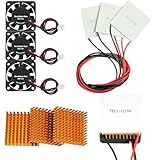
- Peltier cooler:Compatible with for Making Portable Coolers Hot and Cold Water Dispensers 3D Printers CPU Coolers
- Size:40*40*10mm
- Operating current:IMAX=4.3-4.6A(at rated 12V)
- Rated voltage:12V (VMAX:15V starting current 5.8A)
- Commodities include:3Pcs Peltier Cooler Cooling;3Pcs Aluminum Heat Sinks;3Pcs 12V Cooling Fan;16 Pcs Fan mounting screws
Choose a fan and heat sink for practical air rejection
Forced air is usually the straightforward answer when ambient air is cooler than the target, a fin stack can be placed in the airflow, and some noise and moving-part maintenance are acceptable. It avoids the TEC’s extra hot-side burden and can scale by increasing sink area or airflow, subject to noise and pressure-drop limits.
Design the inlet and outlet as carefully as the fan itself. Recirculating exhaust air, blocked filters and a sink with poor fin utilization can erase the expected benefit of a high-rated fan. Use speed control and temperature feedback when the load varies, and provide a safe reduced-performance mode if the fan stalls.
Choose a heat pipe to bridge distance
A heat pipe is appropriate when the source is too far from the best sink for a simple solid spreader, or when a thin passive path is preferred. It can move heat from a processor, power converter or battery region to a fin stack placed where airflow is available. The pipe does not lower the final sink temperature by itself; its value is lower spreading resistance and better placement freedom.
Choose a vapor chamber to spread a concentrated load
A vapor chamber makes sense when a small die or hotspot must feed a larger, flatter sink area. It can reduce local temperature gradients and use more of a fin stack or chassis plate. Confirm the manufacturer’s heat-flux, orientation, thickness and mounting limits for the actual geometry. The NASA overview supplies the family-level mechanism, not a universal performance multiplier.
Independent reader supportYour contribution helps us test, update, and keep practical guides available for everyone.Hybrid arrangements are often the practical answer
Real thermal assemblies frequently combine the technologies. A vapor chamber can spread a processor’s load into a fin stack, a heat pipe can carry that load to a remote radiator, and a fan can move air across the fins. A TEC can provide fine temperature control on a small sensor while its hot side is coupled to a heat pipe and fan-cooled sink. These combinations assign each technology the job it performs best instead of asking one component to handle transport, spreading and final rejection simultaneously.
Hybrid designs add interfaces, controls and failure modes. Model every interface resistance, verify that the final sink can reject the sum of all heat sources, and test the worst combination of ambient temperature, load and airflow. A TEC’s hot-side load must include both the target heat and TEC input; a fan’s airflow must account for the pressure drop introduced by fins, filters and ducts.
A practical selection and validation procedure
- Write the thermal requirement. Record minimum and maximum ambient temperature, continuous and peak heat load, allowed target temperature, duty cycle and whether below-ambient operation is required.
- Map the physical path. Sketch the source, interfaces, spreader, pipe or chamber, sink, airflow route and enclosure boundary. Identify every contact surface and potential recirculation path.
- Choose the passive transport first. If the source and sink are separated, evaluate a heat pipe; if the source is concentrated on a broad flat sink, evaluate a vapor chamber; if neither is needed, a direct sink may be simpler.
- Size final rejection. Select fin area, airflow and ambient margin for the total heat. For a TEC, add electrical input to the cold-side load before sizing the hot-side sink.
- Check mechanical limits. Verify flatness, clamping force, pipe bend radius, chamber footprint, vibration environment and thermal-expansion mismatch. Avoid point loading a ceramic TEC.
- Specify controls and protection. Include fan-speed control or stall detection, TEC current limits, hot-side over-temperature shutdown and sensors at the actual component and sink locations.
- Test the worst case. Measure temperatures after the assembly reaches steady state at maximum ambient and load. Repeat for start-up, airflow restriction, fan fault and the intended orientation. Record electrical power and acoustic or vibration behavior if those drove the design.
- Validate transients. Apply realistic load steps and confirm that the target stays within limits while the pipe, chamber and sink warm. Check that control loops do not oscillate and that a TEC does not cross the condensation threshold.
Common failure modes and fixes
The TEC cold side is not getting cold
- Hot side too warm: increase sink area or airflow, reduce recirculation and verify the interface to the sink.
- Insufficient electrical control: verify polarity, current capability and controller operation; do not exceed the module’s rated current.
- Excessive temperature difference: reduce the requested set-point gap or lower the heat load; TEC capacity falls as the gap grows.
- Poor mechanical contact: inspect flatness, clamping uniformity and interface material. Replace damaged modules rather than tightening one corner.
The fan cooler runs loudly but temperatures remain high
- Check whether the fan is operating on the correct part of its pressure-flow curve.
- Remove blocked filters, cable obstructions and fin dust; confirm that exhaust air is not returning to the inlet.
- Verify that the heat sink is actually making full contact with the heat source and that the sink is large enough for the sustained load.
A heat pipe or vapor chamber appears ineffective
- Confirm that the evaporator is over the heat source and the condenser reaches a cooler sink.
- Check orientation and installation limits for the specific part; wick and gravity behavior are design-dependent.
- Look for crushed bends, damaged seals, poor contact pressure or a sink that cannot reject the delivered heat.
Temperatures are acceptable at first but rise later
- The sink may be absorbing a transient load and approaching its steady-state temperature.
- Ambient air may be heating inside the enclosure because there is no external heat path.
- A fan may be slowing as it warms or accumulating dust; a TEC hot side may be crossing its operating limit.
What the DOE hybrid project means
The U.S. Department of Energy described a 2023 project combining a conventional vapor-compression heat pump with a thermoelectric heat pump for cold-climate operation. Its stated targets included overall seasonal energy-efficiency ratio (SEER) above 18, heating seasonal performance factor (HSPF) above 12 and more than 10% heating-mode energy savings. These are project objectives or anticipated outcomes for that hybrid system, not measured generic performance for a standalone TEC. The project term listed on the page ended in September 2024. Details are available from the U.S. Department of Energy project description.
Do these 3 things before closing this tab:
1Repair Windows errors before they cause bigger problems2Scan for outdated or missing drivers - takes under a minute3Clear out junk files and repair common Windows errorsBottom-line selection rule
Use the technology that matches the dominant problem. Select a TEC when a small target needs active, quiet temperature control and you can remove the added hot-side heat. Select a fan and heat sink when direct air rejection is practical. Select a heat pipe to move heat to a better-located sink, and a vapor chamber to spread a concentrated load across a flat area. In many high-performance assemblies, the best answer is a combination: pipe or chamber for transport and spreading, fan and fins for final rejection, with a TEC added only where active temperature control justifies its power and complexity.
Quick Recap
Product prices and availability are accurate as of the date/time indicated and are subject to change. Any price and availability information displayed on Amazon at the time of purchase will apply.

