Recommended Free Tools
A giant magnetoresistance (GMR) sensor can estimate current without being inserted into a conductor: it detects the magnetic field produced by current and converts that response into an electrical signal. For smart-grid phase monitoring, however, the sensing principle is only the starting point. Sensor position, orientation, calibration, nearby phase conductors, and magnetic interference all affect the reading. Published prototype results and available GMR hardware show promise for measurement and experimentation, but do not by themselves establish a grid-ready phase-monitoring instrument.
How non-contact GMR current sensing works
Current flowing through a conductor creates a magnetic field. A GMR element placed nearby responds to that field, and its output can be used to infer current. The sensor does not need to interrupt the electrical path; as NVE Corporation puts it in its GMR Sensor Catalog, “This application allows for current measurement without breaking or interfering with the circuit of interest.”

As an Amazon Associate I earn from qualifying purchases.
“Non-contact” describes the relationship between the sensor and the measured current path. It does not mean that placement is arbitrary, that the installation is automatically calibrated, or that the reading is immune to other magnetic fields. The 2012 study by Ouyang, He, Hu, and Wang models the response as depending on several factors:
Free tools Windows power users keep installed
One-click scans. No signup required.
- Current magnitude and frequency.
- Temperature and supply voltage.
- The magnetic permeability around the sensor.
- Distance from the conductor and the angle between the field direction and the sensor’s sensitive axis.
- Parasitic magnetic fields in the surrounding environment.
Moving or rotating the sensor, changing the surrounding materials, or bringing another current-carrying conductor nearby can therefore change the measured signal even if the target current has not changed.
#1 Best Overall

- 1. Precision Sensor: Equipped with QMC5883L compatible HMC5883L chip for accurate readings
- 2. Versatile Voltage: Operates on a wide range of 3V-5V power supply
- 3. Extended Measurement: Offers a comprehensive measuring range of +/- 1.3-8 Gauss
- 4. Seamless Connectivity: Features IIC communication protocol for easy integration
- 5. Robust Construction: Utilizes high-quality immersion gold PCB and machine welding for durability
What published performance does—and does not—show
Ouyang, He, Hu, and Wang’s 2012 paper in Sensors characterizes one designed sensor built around a commercial analog GMR chip. For that design, the authors report the following results:
| Measure | Reported result | Scope |
|---|---|---|
| Operating range | 0 to ±5 A | The study’s designed sensor |
| Sensitivity | 28 mV/A | Reported by Ouyang et al., 2012 |
| Linearity | 99.97% | Reported by Ouyang et al., 2012 |
| Maximum deviation | 2.717% | Reported by Ouyang et al., 2012 |
| Frequency response | −1.5 dB at 10 kHz | Reported by Ouyang et al., 2012 |
| Amplitude-response change with thermal compensation | Maximum 0.0335%/°C | Reported by Ouyang et al., 2012 |
These are characterization results for that design, not guaranteed specifications for GMR sensors as a class and not evidence that the prototype is ready for utility deployment. Its reported range should not be treated as covering every normal operating or fault current a grid application may encounter.
Rank #2
Why phase-current monitoring is a geometry problem
A sensor near one isolated wire has a simpler job than a sensor installed among multiple phase conductors. Every nearby current-carrying conductor contributes a magnetic field, and the GMR element responds to the combined field according to its position and sensitive axis. A reading intended to represent one phase can therefore be affected by adjacent phases unless the arrangement and signal interpretation account for their contributions.
A 2019 GMR smart-grid article discusses the difficulty of straight-wire sensing when the field at the sensor is small and the measurement is sensitive to distance and relative position. It describes a flux-guided structure as part of its design. That example underscores that the conductor and magnetic-field geometry can be part of the sensor system—not merely installation details.
Rank #3

- This is a digital compass sensor based on BMM150, supports magnetic field measuring in three perpendicular axes, I2C / SPI interfaces, can be used in robot navigation and positioning, electronic compass, magnetic heading devices, etc.
- Supports I2C/SPI interface communication, I2C interface by default, SPI switchable via onboard resistor
- Onboard voltage translator, compatible with 3.3V/5V level
- Can be used in robot navigation and positioning, electronic compass, magnetic heading devices, etc.
- Comes with online development resources and manual (examples for Raspberry Pi / Raspberry Pi Pico / Arduino / ESP32)
Design questions to settle before choosing a sensor
- Phase geometry: Where will the sensor sit relative to each conductor, and how will cross-coupling from adjacent phases be characterized?
- Operating and fault range: What current range must be measured, and what happens if the signal exceeds the sensor’s linear range or saturates?
- Bandwidth: What frequency content must the monitor capture, and does the complete sensing circuit—not just the GMR element—support it?
- Accuracy over conditions: How will sensitivity, linearity, and thermal drift be checked across the intended operating environment?
- Isolation and installation: What electrical isolation is required, and how will the sensor be mounted without disturbing conductor geometry?
- Calibration and interference: How will calibration account for sensor position, orientation, nearby magnetic sources, and changes after installation?
The cited studies do not establish one universal arrangement for measuring all three phases, nor do the cited product pages identify a grid-qualified phase-monitoring instrument. An implementation therefore needs validation in its own conductor layout and operating conditions.
GMR prototype evidence versus available hardware
Published research and manufacturer hardware answer different questions. The 2012 paper reports results for a particular designed sensor; NVE’s product pages describe components and an evaluation board for building or comparing circuits. The listed products are useful starting points for prototyping, but they are not complete phase-monitoring systems.
Rank #4
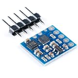
- 3-Axis Magnetoresistive Sensors and ASIC in a 3.0x3.0x0.9mm LCC Surface Mount Package. Small Size for Highly Integrated Products. Just Add a Micro Controller Interface, Plus Two External SMT Capacitors. Designed for High Volume, Cost Sensitive OEM Designs. Easy to Assemble & Compatible with High Speed SMT Assembly. 12-Bit ADC Coupled with Low Noise . AMR Sensors Achieves 5 milli-gauss . Resolution in ±8 Gauss Fields.
- Enables 1° to 2° Degree Compass Heading Accuracy; Built-In Self Test; Enables Low-Cost Functionality Test after Assembly in Production; Low Voltage Operations (2.16 to 3.6V); and Low Power Consumption (100 μA); Compatible for Battery Powered Applications; Built-In Strap Drive Circuits; Set/Reset and Offset Strap Drivers for Degaussing, Self Test, and Offset Compensation; I2C Digital Interface ; Popular Two-Wire Serial Data Interface for Consumer Electronics; Lead Free Package Construction;
- The module designed for low-field magnetic sensing with a digital interface for applications. The module includes our state-of-the art, high-resolution HMC118X series magneto-resistive sensors plus an ASIC containing amplification, automatic degaussing strap drivers, offset cancellation,and a 12-bit ADC that enables 1° to 2° compass heading accuracy. The I2C serial bus allows for easy interface. The HMC5883L is a 3.0x3.0x0.9mm surface mount 16-pin leadless chip carrier (LCC).
- The HMC5883L utilizes Honeywell’s Anisotropic Magnetoresistive (AMR) technology that provides advantages over other magnetic sensor technologies. These anisotropic, directional sensors feature precision in-axis sensitivity and linearity. These sensors’ solid-state construction with very low cross-axis sensitivity is designed to measure both the direction and the magnitude of Earth’s magnetic fields, from milli-gauss to 8 gauss.
- 【PIN CONFIGURATIONS】 SCL:Serial Clock – I2C Master/Slave Clock; VDD:Power Supply (2.16V to 3.6V); NC:Not to be Connected; S1:Tie to VDDIO; NC:Not to be Connected; NC:Not to be Connected; NC:Not to be Connected; SETP:Set/Reset Strap Positive – S/R Capacitor (C2) Connection; GND:Supply Ground; C1:Reservoir Capacitor (C1) Connection; GND:Supply Ground; SETC:S/R Capacitor (C2) Connection – Driver Side; VDDIO:IO Power Supply (1.71V to VDD);
| Item | Published or manufacturer-stated information | |
|---|---|---|
| Designed sensor in Ouyang et al., 2012 | 0 to ±5 A; 28 mV/A sensitivity; 99.97% linearity; 2.717% maximum deviation; −1.5 dB at 10 kHz; maximum amplitude-response change of 0.0335%/°C with thermal compensation | Study characterization of one design in Sensors, 2012; not a general GMR specification |
| NVE AAL024-10E | 1–10 A current measurement range; 0.15–1.05 mT field measurement range; bridge output; cross-axis sensitivity; 2.5 × 2.5 mm DFN6 package | Manufacturer specifications on NVE’s product page, accessed in 2026; check the current datasheet and intended circuit geometry |
| NVE AG903B-07E evaluation board | Three separable AAL024-10E modules optimized for 0–0.75 A, 0–5 A, and 0–50 A | Manufacturer description of an evaluation board; not a complete phase-monitoring device |
The current range figures in this table describe different things: the 2012 values belong to a characterized sensor design, the AAL024-10E figures are manufacturer specifications, and the AG903B-07E figures describe configurations on an evaluation board. They should not be treated as directly comparable guarantees for a finished monitor.
How to evaluate a GMR phase-sensing design
Compare complete sensing arrangements rather than selecting a sensor by headline sensitivity alone. A useful evaluation should cover:
Best Value
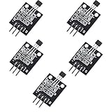
- Hall Switch Integrated Circuit Using hall Effect Principle
- Uses The Semiconductor Integrated Technology Manufacturing Magnetic Susceptibility of the Circuit
- Its Input For the Magnetic Induction Intensity, the Output is a Digital Voltage Signal
- Measurement range, expected overloads, and saturation behavior.
- Sensitivity and linearity across the intended current range.
- Frequency response of the assembled sensor and signal-conditioning circuit.
- Temperature behavior and any compensation required.
- Electrical isolation and whether the installation changes or interrupts the measured path.
- Packaging, mounting repeatability, and the calibration burden.
- Response to adjacent conductors, cross-axis fields, and other magnetic interference.
The 2012 paper places GMR among several approaches used in power-system current sensing, including current transformers, Rogowski coils, shunts, fiber-optic current transformers, fluxgate sensors, and Hall sensors. Their trade-offs differ; for example, a shunt interrupts the measured path, while magnetic and optical approaches have their own isolation, bandwidth, size, cost, and environmental considerations. The paper’s comparison is context for evaluating options, not a universal ranking.
Where to start prototyping
NVE’s AG903B-07E evaluation board provides three separable AAL024-10E modules with manufacturer-stated configurations optimized for 0–0.75 A, 0–5 A, and 0–50 A. It can help an engineer explore sensing ranges and circuit behavior. The AAL024-10E is a component for custom electronics, not a standalone meter. NVE’s application-note index also lists “Current Measurement Using GMR Sensors” and “High-Current Sensing PCB Design” for additional guidance on conductor geometry and PCB current sensing.
For a phase-monitoring prototype, test the intended conductor arrangement, sensor axis, operating range, thermal conditions, and nearby-phase effects together. A single component specification or evaluation-board configuration cannot establish accuracy, reliability, or suitability for a utility installation.
Quick Recap
Product prices and availability are accurate as of the date/time indicated and are subject to change. Any price and availability information displayed on Amazon at the time of purchase will apply.

