Do these 3 things before closing this tab:
1Fix the driver behind crashes, sound loss and screen glitches2Repair Windows errors before they cause bigger problems3Scan for outdated or missing drivers - takes under a minuteIt depends on which transformer winding the center tap belongs to and on the PHY’s specified circuit. A PHY-side tap may connect to a filtered supply in one design or couple to ground through a capacitor in another. A cable-side tap may be part of a Bob Smith termination network or a PoE power path. Identify the winding, then follow the exact PHY, magnetics and—if applicable—PoE reference designs; there is no universal power-or-ground rule.
First identify the winding
The PHY (or chip) side connects to the Ethernet PHY’s MDI pins. The cable (or line) side faces the RJ-45 connector. A center tap is the connection to the midpoint of a transformer winding; its role depends on which winding it serves and how that circuit is designed.

As an Amazon Associate I earn from qualifying purchases.
Do not identify a tap by its position in a schematic or by a MagJack pin number alone. Check the magnetics or MagJack datasheet and trace the pin to its winding. The TI DP83867 datasheet names Pulse Electronics HX5008FNL as a recommended discrete magnetics example and provides an accompanying reference circuit (TI DP83867IR/CR datasheet, Rev. G).
Crashes, No Sound, or Screen Glitches?
Random freezes, missing sound and display glitches usually trace back to one bad driver. Find and replace yours safely.Free scan · under a minutePC Slower Than It Used to Be?
A free scan shows the junk files, broken settings and background clutter dragging Windows down - then fixes them in one click.Free scan · Windows 10 & 11What the two sides do
| Winding side | Typical role | What the cited examples show | What to check |
|---|---|---|---|
| PHY / chip side | PHY common-mode bias or AC return | In TI’s DP83867 example, each tap is isolated from the others and coupled to ground through a recommended 0.1 µF capacitor. A separate TI application-report example connects the microcontroller-side tap to filtered 3.3 V. | Use the selected PHY’s datasheet and reference circuit. Do not substitute another PHY’s connection. |
| Cable / RJ-45 side | Common-mode termination; potentially a PoE power path | Examples use a Bob Smith network with 75 Ω resistors and a high-voltage capacitor to chassis. PoE designs may also inject power through cable-side center taps. | Check the magnetics, PHY, termination and PoE controller guidance together, including the required isolation and grounding scheme. |
PHY-side taps: power or capacitive coupling?
Ground through a capacitor in the DP83867 example
TI’s DP83867IR/CR datasheet, Rev. G, §9.2.1.1 and Figure 9-2, says each PHY-side center tap must be isolated from the others and connected to ground through a decoupling capacitor; it recommends 0.1 µF. This is a capacitive connection, not a direct DC short to ground. The example’s cable-side network uses 75 Ω resistors and a 1 nF, 2 kV capacitor. These are values for that cited design, not universal Ethernet requirements (TI DP83867IR/CR datasheet).
#1 Best Overall

- 1CT:1CT
- 350MICROHENRIES INDUCTANCE
- DATACOM TRANSFORMER
- ETHERNET APPLICATION(S)
- LAN TRANSFORMER
Filtered 3.3 V in another TI example
A TI application report instead says to connect the transformer center tap on the microcontroller side to 3.3 V, with filtering. It specifies at least 0.1 µF for a solid-plane connection or at least 1 µF for a trace connection. Its RJ-45-side Bob Smith example uses 75 Ω resistors and a 1000 pF capacitor rated at least 2 kV to chassis ground. Those instructions belong to that report’s design; they do not override the selected PHY’s own reference circuit (TI application report, Feature-Specific Design Information).
Microchip provides another example: the LAN9646 hardware checklist calls for chip-side transformer center taps to be independently connected to signal ground through 0.1 µF capacitors and recommends magnetics with isolated center taps (Microchip LAN9646 Hardware Design Checklist).
Rank #2

- Main Chip: ENC28J60-I/SO
- The board 25MHZ crystal
- RJ45 connector HR911105A isolation transformer
- Power supply 3.3V
Cable-side taps: termination and PoE are separate functions
A cable-side center tap may be part of a Bob Smith common-mode termination network. In the cited examples, 75 Ω resistors connect the relevant lines to a high-voltage capacitor that references chassis ground. Follow the exact PHY and magnetics design for the resistor arrangement, capacitor value and grounding. Chassis ground and signal ground are not interchangeable labels: do not join them directly just because both appear as ground symbols in a drawing.
Quick wins for a faster PC:
Clear out junk files and repair common Windows errorsFree Scan →Scan for outdated or missing drivers - takes under a minuteDriver Scan →PoE is a separate consideration. Depending on the Ethernet mode and pair arrangement, PoE can deliver power through cable-side transformer center taps. That does not make the PHY-side center tap a PoE rail. TI describes center-tap injection in its PoE application brief, and Analog Devices’ LTC4255 article notes that the 48 V line supply must be isolated from PSE chassis ground to maintain link isolation. Use the relevant PSE/PD controller guidance and preserve the required isolation (TI SNLA395 application brief; Analog Devices LTC4255 article).
Rank #3
How to check a schematic before wiring
- Find the exact PHY and magnetics documents. Label each winding as PHY/chip side or line/cable/RJ-45 side using the component pinout, not physical placement in the drawing.
- Read the PHY’s MDI or magnetics reference circuit. Record what it specifies for each PHY-side tap: supply bias, capacitor coupling to ground, another arrangement, or no separate connection.
- Check the magnetics pinout and internals. Determine whether taps are separate, internally joined or absent, and verify the part’s electrical requirements against the PHY.
- Review cable-side termination and PoE independently. If PoE is present, include the PSE/PD controller design guidance and isolation requirements rather than treating PoE as a PHY bias connection.
- Match the reference design’s grounding. Distinguish signal ground from chassis ground and replicate the intended connection; a capacitor to ground does not mean the tap is directly DC-grounded.
If the board’s connection is still unclear, the decisive information is the PHY part number, the magnetics datasheet or MagJack pinout, the Ethernet mode and whether PoE is used. Without those, a safe connection cannot be inferred from the phrase “center tap” alone.
Quick Recap
Best Value
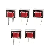
- Advantages:high pressure and stable performance
- AC impedance : EI14 600 : 600 Ohm
- Inductance:290mH (±20%)
- Quality &wire diameter : QA-1 0.06MM
- Alternating-current impedance value : 600
Rank #4

- Input Voltage: 100V-240V 50/60Hz
- Safety & Durable: Level VI Energy Efficiency
- Overvoltage and Shortcircuit protection
- Replacement for 12V 1A Netgear Prosafe GS605 GS608 GS116 GS108 Ethernet Switching Transformer Power Supply Cord Mains PSU AC110-240V
- Cable Length: 5 Feet
Product prices and availability are accurate as of the date/time indicated and are subject to change. Any price and availability information displayed on Amazon at the time of purchase will apply.

