A PC that shows no power, no boot, or no display does not automatically have a failed motherboard. A power-supply fault, loose connector, unsupported CPU or BIOS version, bad memory, graphics problem, monitor or cable issue, and even a front-panel switch can produce the same symptoms. Diagnose in a fixed order: establish what the machine is doing, verify power and connections, confirm CPU/BIOS support, check the display path, isolate RAM and graphics, read board diagnostics, and then run a minimal POST test. Only after those checks repeatedly fail should the motherboard become a leading suspect.
What “no power,” “no boot,” and “no display” actually describe
Use precise terms before changing parts. They identify different stages of startup and prevent a display problem from being mistaken for an electrical failure.
As an Amazon Associate I earn from qualifying purchases.
| Symptom | What you observe | Likely stage to investigate first |
|---|---|---|
| No power | No fans, lights, or other apparent startup activity when the case button is pressed. | Outlet, power cord, PSU rear switch, PSU cables, motherboard power connectors, and the case switch circuit. |
| No boot | The system receives power but does not complete POST or reach the operating-system loader. | CPU support and BIOS version, RAM, graphics initialization, firmware settings, and board diagnostics. |
| No display | Fans or LEDs run, but the monitor reports no signal or remains blank. | Monitor input, video cable, correct output socket, GPU power/seating, integrated-graphics support, RAM, and POST status. |
A spinning fan proves only that some power is present. It does not prove that the CPU executed firmware, that memory training succeeded, or that POST completed. Record exactly what happens: whether fans twitch or spin continuously, which LEDs illuminate, whether the machine restarts in a loop, any beep pattern, recent hardware or firmware changes, and whether the symptom began after moving the case or cleaning it.
Safety and preparation before opening the case
- Shut the PC down, switch the PSU off, remove the AC lead, and press the case power button once to discharge residual power before reseating parts or clearing CMOS.
- Work on a non-carpeted surface, touch the case chassis before handling components, and hold expansion cards and memory by their edges.
- Stop immediately if you see a scorched area, swollen component, melted connector, liquid residue, or smell burning. Do not continue energizing visibly damaged hardware.
- Have the exact motherboard model and revision, CPU model, memory kit details, graphics-card model, PSU model, and the board manual available. Connector names, diagnostic meanings, and reset procedures differ by model.
- Keep a phone or notebook record of every change. Reversing one change at a time is far more informative than replacing several parts together.
Step 1: Check the external power path
Verify the wall connection and PSU switch
Plug a lamp or another known-working device into the same outlet. If a power strip or surge protector is used, confirm its switch is on and bypass it temporarily with a direct wall connection. Confirm the PSU rocker switch is in the on position (usually marked “I”), not “O,” and that the AC cable is fully inserted at both ends. A tripped household breaker or failed extension lead can look exactly like a dead PC.
#1 Best Overall

- [Standard Interface] This pc diagnostic card features standard pci and isa interfaces, making it easy to access desktop pcs.
- Post Code Display] With a 4 digit display, the card shows the current and previous error codes, aiding in troubleshooting.
- [Compatibility] Compatible with all motherboards with pci and isa bus slots, this diagnostic card is suitable for a wide range of computers.
- [Hexadecimal Display] The card's dot hexadecimal readout displays accurate power on self test (post) status codes, providing detailed diagnostic information.
- [Remote Display Function] The motherboard diagnostic card comes with a self-checking remote display function for easy viewing of post codes.
Reseat the motherboard power plugs
With AC power removed, press the motherboard’s required 24-pin ATX connector firmly into its socket until its latch engages. Check the separate CPU power connector near the processor socket (commonly a 4-pin, 8-pin, or split 4+4 connector) and make sure the plug is the CPU/EPS lead, not a similarly shaped PCIe lead. Some boards have additional CPU power sockets; follow the manual for which are required for your processor. Never force a connector or mix modular PSU cables from a different PSU.
Separate a case-switch fault from a board fault
If standby lights are present or fans start when the PSU is switched on but the case button does nothing, inspect the two-wire front-panel power-switch lead and its header location. A loose plug, a lead on the wrong pins, or a failed button can prevent startup while the motherboard remains functional. MSI’s official no-power and no-display procedure documents checking this connection. Do not short header pins as a test unless the exact motherboard manual identifies the correct power-switch pins and you can work safely; an incorrect short can damage hardware.
Step 2: Confirm CPU, socket, and BIOS compatibility
Look up the exact board model and revision on its manufacturer support page, then open the CPU support list. Check that your processor’s precise model appears and note the minimum BIOS version shown beside it. A board can be electrically healthy yet fail to POST with a processor released after the BIOS installed on the board. This is especially common when a new CPU is fitted to older inventory.
- Read the model printed on the board or its original box; do not rely on a chipset name alone.
- Find the CPU support list and required BIOS version for that model and revision.
- Compare the installed BIOS version, if known, with the requirement. If the system can enter firmware setup, the version is usually on the main or information page.
- Check socket alignment and inspect for bent socket contacts, contamination, or a cooler mounted with uneven pressure. Disconnect power before inspecting.
- If an update is needed, follow the board’s documented flash procedure and power requirements. Some models can update without a supported CPU, while others cannot; do not assume a generic method works.
ASUS and MSI both place CPU/BIOS compatibility near the beginning of their respective troubleshooting flows: ASUS’s no-power/no-boot/no-display guidance and MSI’s procedure linked above. Until compatibility is confirmed, replacing either the CPU or motherboard is premature.
Rank #2

- 【1】*** MUST see the 3rd pictures in listing that highlights the correct PCI slots to work ***. Using this kit wrongly on motherboard other PCIe port is not the reason of "Doesn't Work". Please make sure the motherboard has PCI slot before placing the order. The Large Desktop PC motherboard diagnostic card is NOT a PCIe card but a Standard PCI card. If the PC has PCIe express slots only, please see my other listing with the "V8 PCIe Diagnostic Kit" instead. ***DO NOT push the Wrong pins with excess force to avoid issue. MUST MAKE SURE PSU 4 / 6 / 8 pin power connector pins match and fit to the tester exact same 4, 6, 8 pins CORRECTLY although the PSU tester is fault tolerant and preventive.
- 【2】This starter kit comes with 1 large PCI test board and 1 small laptop test board for the old desktop PCs and old laptops diagnosis respectively. The large test board comes with【BIOS SPEAKER】to get the desktop PC motherboard Bios beep codes. The 【motherboard power switch cable】is nice to quick check the sticky or damaged PC motherboard power switch button and cable causing no power ON issue. The【the Anti Static Wrist Strap】is a plus to help discharge static during the PC repairs. The 【ATX PSU tester】in this kit is either Blue or Black Color with EXACT same features to quick test the 20/24 pins PC ATX PSUs.
- 【3】Nice starter kit for old computers no Power On / Auto Power OFF / no POST / no Display / no Boot ...etc. diagnosis. No need to swap Known Good Parts in the computer repairs. Save time and money!! All parts are packed well and stored neatly in a nice 【Portable Carrying Storage Case】. A overall great starter kit to add to our tool boxes! Great for computer class learning and old PCs quick troubleshooting needs as well.
- 【4】Please see the listing for the instruction PDFs. *****【On the listing page】, scroll down to after the "Product Information" table the "Product guides and documents" section, BOTH the pictorial "User Guide (PDF)" and the "User Manual (PDF)" are needed. *****. ***** Besides, please DO NOT discard the ITEM PACKING Included Paper Manual Note Printout since that also contains the complete Instruction folder info!!! *****
- 【5】Online Easy Guide and Pictorial Manuals to guide step by step with complete list of codes description. Downloadable manuals to stay updated. Welcome to conact if any question or need helps. Quality Genuine Computer Hardware Diagnostic Test Starter Kit with Free Lifetime Customer Service Supports from 29 years professional computer hardware work experienced seller.
Step 3: Eliminate the display path before diagnosing POST
Check the monitor itself
Confirm the monitor’s power indicator is on, select the input that matches the connected port (HDMI, DisplayPort, DVI, or VGA), and open its on-screen menu. If the menu does not appear, troubleshoot the monitor or its power before the PC. A monitor left on the wrong input reports “no signal” even when the computer is working.
Use the correct video output
When a discrete graphics card is installed, connect the cable to the card’s output, not the motherboard’s video socket. The motherboard socket works only when the CPU includes an active integrated GPU and the firmware supports using it. Conversely, if you are testing without a discrete card, use the motherboard output only with a CPU that has integrated graphics. Push the cable fully into both sockets and try a known-good cable or display when available.
Interpret a blank screen with other signs
Observe whether the keyboard LEDs respond, whether the monitor briefly wakes during startup, and whether the system reaches the usual login sound. A blank screen with normal operating-system activity points toward the GPU, cable, monitor, or output selection rather than motherboard POST. A blank screen accompanied by a persistent CPU, DRAM, or VGA diagnostic light requires hardware isolation instead.
PC Slower Than It Used to Be?
A free scan shows the junk files, broken settings and background clutter dragging Windows down - then fixes them in one click.Free scan · Windows 10 & 11Outdated Drivers Are Slowing You Down
One free scan finds every outdated or missing driver and matches the right update for your exact hardware.Free scan · exact hardware matchStep 4: Reseat and isolate memory
Memory that is slightly unseated, installed in an unsupported combination, or failing during training can stop POST and leave the display blank. Turn the PSU off, unplug AC power, and remove the side panel. Release the slot latches, remove each module, and reinstall it evenly until both latches lock.
Rank #3
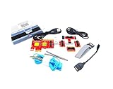
- ATTN : Please DO study the listing page the "Product Guides and Documents" section, the "Instructions for Use (IFU) (PDF)" guide for all manual links at the end of the PDF, to use this kit correctly and easily. 【The item PACKING】 includes the paper printout with the same Complete Instruction Folder with PDFs and APP. 【Only use the tested APP in the folder】 【BOTH 64bit for Newer Androids and 32bit Manufacturer APP】 are available, passed the Android security scan checks and Google Play pending. MUST use the Android APP to display results on the screen, NO Traditional DIGITAL Display to show the POST codes, Great Ease to save hassles of diagnostic codes lookup one by one manually.
- Easy To Use Unique USB Diagnosis with Videos and PDF Guides. 【MUST study the Guides Before Use】 New latest smartphone technology in using the USB ports ( Standard USB / micro USB / Type C ) to diagnose the computers. 【NOT just getting the electric power but RUNNING the Diagnosis Data through USB ports】. A very powerful Essential Nice Handy computer repair tool kit for quick help on diagnosing Desktop PC, Server, Laptop, All-in-one PC, Android Smartphone / Tablet, customized built miniPC and Mac machines ... etc. A great motherboard tester diagnostic kit that provides the most accuracy and effectiveness in making the computer troubleshooting and repairs much easier.
- USB Diagnosis Unique Feature - Save hassles of taking the dusty PCs or laptops apart. Follow the English PDF user guides to power on and let the Android APP to work with this new test kit to auto scan the motherboard for faulty components quickly. When testing different PCs together, make sure follow the listing User Guide(PDF) to see 【Latest Updates with PRECAUTIONs and Extra Tech Tip】 to UNPLUG the USB cable between each test and restart to clear the last cached working motherboard diagnosis data. The ONBOARD USB cable is needed to plug to the Android charger, the other dedicate USB cable connects to motherboard USB port. Connect this 2 USB cable wrongly causes the unstable connectivity.
- All-in-one Multiports support - Different complete bus connector adapter parts included. Made of quality PCB, transistors and capacitor components. Direct pinpointing the faulty motherboard components to greatly reduce the costs yet increase the effectiveness in the computer diagnostic repairs. Videos and the PDFs instructions please see the listing "Videos" section and the "Product guides and documents" section for more details.
- Tested and brought to you by 29 years IT Professionals This kit works with all machines with USB ports including New Old Desktop PC and Laptop Computers, IBM compatible, Mac machines (using USB), Android devices Smartphones and Tablet PCs. Comes with Step by Step Easy Guides, videos instructions, PDF pictorial manuals with Easy Flowcharts and Latest Updates with Precautions. Great for PC Technicians, Computer Owners, Computer Class Student Learners and PC DIY Lovers, Hardware Traders, professionals and novices . Nice Essential must have to add to our computer tool boxes.
- Leave only one memory module installed.
- Place it in the slot the manual recommends for a single module—often the second slot from the CPU, but not universally.
- Attempt startup and allow extra time for memory training if the board indicates that it is training.
- If it fails, power down and test the same module in the board’s other recommended single-module slot.
- Repeat the process with each module individually. Keep notes on which module and slot produce a different result.
Do not treat a DRAM indicator as proof that a particular stick is bad. The light identifies the stage at which POST stopped; a CPU contact problem, firmware setting, or board slot can produce the same indication.
Step 5: Check the graphics card and its power
With the system disconnected from AC, verify that the graphics card is fully seated in the primary PCIe slot and that its retention latch is closed. Confirm every required auxiliary PCIe power plug is attached directly from the PSU. A partially inserted card or missing power lead can leave fans running while producing no display.
If the processor has integrated graphics, remove the discrete card and test the motherboard video output with one memory module. If that produces video, the fault is narrowed to the card, its power, the slot, or the display path. If the CPU lacks integrated graphics, this test cannot work; use a known-good discrete card instead. A VGA debug light narrows the search but does not establish that the card is irreparable or that the motherboard slot is defective.
Free tools Windows power users keep installed
One-click scans. No signup required.
Step 6: Use Q-LEDs, debug LEDs, and beep codes as clues
Many boards provide CPU, DRAM, VGA, or BOOT indicators. Note which light remains on after the initial blinking sequence, then consult the manual for that exact model. ASUS explains the purpose and limitations of its Q-LED system in its Q-LED troubleshooting guide. The indicator identifies a POST category, not a guaranteed failed part.
Rank #4
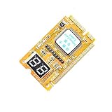
- 3 in 1 tester.
- For PCI, PCI-E, and LPC.
- Diagnostic post-test card.
- Diagnostic post-test card.
- Easy to use.
| Persistent indicator | First checks | Why it is not conclusive |
|---|---|---|
| CPU | CPU power plug, socket contacts, cooler pressure, supported processor, and BIOS version. | A power-delivery, socket, or firmware issue can imitate a dead CPU or board. |
| DRAM | One module, recommended slot, seating, module-by-module test, and cleared overclock settings. | The memory controller, CPU contact, slot, or firmware can stop at the same stage. |
| VGA | Card seating, auxiliary power, output port, integrated-graphics test, cable, and monitor input. | The card, cable, monitor, slot, or firmware may be responsible. |
| BOOT | Storage connection and boot-device settings after POST has completed. | A BOOT light generally means the board progressed farther than a CPU/DRAM/VGA stop; it does not by itself indicate board failure. |
Some boards include a small two-digit POST code display; its codes are model-specific and must be read in the manual. If the board has no built-in speaker, a compatible motherboard POST speaker or PC case buzzer can provide beep diagnostics when the board supports them. Connect it only to the documented speaker header.
Beep meanings vary by firmware and board. ASUS’s buzzer troubleshooting reference gives examples such as one long/two short beeps for memory, one long/three short for graphics, and one long/four short for CPU-fan, temperature, or voltage conditions. Treat those as examples, not a universal codebook; count the exact pattern and verify it against your model’s manual.
Independent reader supportYour contribution helps us test, update, and keep practical guides available for everyone.Step 7: Run a minimal POST test
A minimal POST test removes variables. MSI describes a setup containing the CPU, CPU cooler, one memory stick, PSU, and monitor, with external devices and other add-in cards disconnected. This is an isolation procedure, not a performance or stress test.
What’s actually slowing this PC down?
Pick the symptom - the matching free tool is one click away.
- Shut down, switch off the PSU, unplug AC power, and press the case button once.
- Disconnect USB devices, storage drives, front USB accessories, add-in cards, and all external peripherals except the monitor.
- Remove extra memory modules and leave one module in the manual’s recommended slot.
- Leave the CPU and cooler installed, and connect the 24-pin motherboard, required CPU power, and cooler-fan header.
- Keep the graphics card only if the CPU has no integrated graphics; otherwise test the integrated output first. Connect the monitor to the output being tested.
- Reconnect AC power, switch on the PSU, and start the system. Watch the diagnostic LED sequence and listen for beeps.
- If it reaches firmware setup or produces a changed, meaningful diagnostic result, power down and reconnect one removed item at a time. Test after each addition.
When the machine works in minimal configuration, the last device reconnected before failure is the leading suspect. A USB device, storage drive, add-in card, shorted front-panel accessory, or cable can prevent startup even though the motherboard is healthy. If the minimal setup still fails, continue with the compatibility, memory, graphics, and CMOS checks rather than declaring the board dead.
Best Value

- [MULTI-INTERFACE COMPATIBILITY] Supports PCIe, mini PCIe, and LPC interfaces for comprehensive diagnostics across various motherboard types including desktops and laptops. Features automatic recognition of power modules with .
- [COMPREHENSIVE SYSTEM DIAGNOSTICS] Monitors power supply, CPU, memory, graphics card, and hard disk status through multi-channel LED indicators. Provides real-time analysis of motherboard health and component functionality.
- [PROFESSIONAL TOOLKIT] Includes diagnostic card, connecting wires, terminals, adapter cards, and flat cables for complete troubleshooting. Designed for technicians working with , Gigabyte, and motherboards.
- [USER-FRIENDLY DESIGN] Features plug-and-play operation with clear LED indicators for easy interpretation. Compact 78x51.8mm size with portable round hole design for convenient carrying and storage.
- [ADVANCED DIAGNOSTIC CAPABILITIES] Tests 3VSB power, MOBO status, CPU module, DRAM memory, VGA graphics, and PCH south bridge. Displays DP decimal point and CLK signals for detailed analysis.
Step 8: Clear CMOS when a firmware setting may be blocking startup
An unsuccessful overclock, wrong memory profile, incorrect boot setting, or other firmware change can cause no boot or no display. Clear the settings only when the symptom began after such a change or the troubleshooting flow calls for it.
- Shut down the PC, turn the PSU off, unplug the AC cable, and discharge the system.
- Use the exact clear-CMOS button or jumper procedure in the motherboard manual. MSI may label a jumper JBAT1, but labels and pin locations differ across manufacturers.
- If the manual permits temporary battery removal, follow its stated orientation and waiting procedure; do not guess how long to leave it out.
- Restore the battery, reconnect AC power, and start with default firmware settings.
- Re-enter setup only after a successful POST, then apply changes one at a time.
Never move a jumper or remove a battery while the board is energized. Clearing CMOS erases custom settings; it does not repair damaged silicon, and it should not be used as a substitute for checking CPU support or power connections.
How to decide whether the motherboard is a plausible failure
Use evidence rather than a single symptom. A motherboard becomes a stronger suspect when all of the following are true:
Quick wins for a faster PC:
Clear out junk files and repair common Windows errorsFree Scan →Fix the driver behind crashes, sound loss and screen glitchesFind Drivers →Repair Windows errors before they cause bigger problemsFix Now →- The outlet, AC cable, PSU switch, 24-pin connector, CPU power connector, and case-switch lead have been verified.
- The processor is listed for the exact board revision and the installed BIOS meets its requirement.
- A known-good monitor and cable are connected to the correct output, with graphics-card power and seating checked.
- Each memory module has been tested individually in the recommended slot, and graphics hardware has been isolated where possible.
- CMOS has been reset using the documented method when firmware settings are a plausible cause.
- The minimal CPU/cooler/one-module/PSU/monitor configuration still fails in a repeatable way, with the same board-specific indicator or code.
Even then, the result does not prove a board-level electrical failure. A PSU that sags under load, a CPU with a memory-controller fault, damaged socket contacts, or a defective RAM module can imitate it. ASUS’s main troubleshooting sequence is available at https://www.asus.com/us/support/faq/1042632/, and MSI’s model-independent sequence is at its support page; use them alongside the exact manual. Contact the motherboard manufacturer or a qualified repair professional before purchasing an expensive replacement, especially when substitution testing would risk additional damage.
When replacement is justified—and what must match
Do not buy a replacement board simply because the PC has no display. If a technician or manufacturer confirms the board is defective, compare the replacement against the entire system:
| Compatibility item | What to verify |
|---|---|
| CPU socket and generation | The socket must physically match, and the board’s CPU list must include the processor with an appropriate BIOS version. |
| Chipset and firmware | Required features, firmware support, and any update method available before the CPU is installed. |
| Memory | DDR generation, module capacity, slot count, and support for the existing kit; DDR4 and DDR5 are not interchangeable. |
| Form factor | ATX, microATX, Mini-ITX, or another size must fit the case standoffs and rear opening. |
| Power connectors | 24-pin ATX, CPU EPS connectors, and any additional requirements must be available from the PSU. |
| Expansion and storage | PCIe slots, M.2 sockets, SATA ports, and lane-sharing arrangements must suit the GPU and drives. |
| Front-panel and cooling headers | Case switches, USB/audio leads, fan plugs, and cooler mounting hardware must connect to the new layout. |
Back up data before any replacement work. A motherboard swap can trigger operating-system reactivation, driver changes, or storage-mode differences, but those are separate from diagnosing the original no-power, no-boot, or no-display symptom.
A compact decision path
- No lights or fans: test outlet, strip, AC cable, PSU switch, 24-pin and CPU power, then the case-switch lead.
- Fans run, no display: verify monitor input and cable, use the correct GPU or integrated output, and check GPU power.
- POST stops at a diagnostic LED: follow that category’s checks, then test one memory module and remove add-in devices.
- Recent CPU or firmware change: verify support and BIOS version, then clear CMOS using the manual.
- Still failing in minimal setup: document the repeatable code or LED pattern and seek manufacturer or professional diagnosis before replacement.
This sequence distinguishes a power-delivery problem from a POST-stage problem and a display-path problem without assuming that the motherboard is at fault. The exact connector names, indicator behavior, BIOS requirements, and reset steps remain model-dependent, so the current manual for the board in front of you is the final authority.
Do these 3 things before closing this tab:
1Repair Windows errors before they cause bigger problems2Fix the driver behind crashes, sound loss and screen glitches3Clear out junk files and repair common Windows errorsQuick Recap
Product prices and availability are accurate as of the date/time indicated and are subject to change. Any price and availability information displayed on Amazon at the time of purchase will apply.

