Outdated Drivers Are Slowing You Down
One free scan finds every outdated or missing driver and matches the right update for your exact hardware.Free scan · exact hardware matchPC Slower Than It Used to Be?
A free scan shows the junk files, broken settings and background clutter dragging Windows down - then fixes them in one click.Free scan · Windows 10 & 11Start by treating every wet spot as an undiagnosed condition, not proof of a leak. Record where and when you found it, check leak-sensor and building-management-system alarms, then compare coolant and nearby surface temperatures with the local air dew point. A surface at or below dew point can sweat; a confirmed fluid escape requires the installed system’s emergency isolation and OEM service procedure. For systems without a coolant distribution unit (CDU), ASHRAE Technical Committee 9.9 recommends facility water at least 3.6°F (2°C) above room ambient dew point.
How do I troubleshoot a leak in a data center liquid cooling system?
Use a controlled sequence that separates observation, diagnosis, response and repair. Do not open a live loop, disconnect a quick-coupling or close an arbitrary valve just because moisture is visible. Liquid-cooling architectures differ in coolant, pressure, valve arrangement, sensor coverage and shutdown dependencies.
As an Amazon Associate I earn from qualifying purchases.
- Make the area safe and preserve the evidence. Follow your facility’s electrical and water-emergency rules. Keep people away from energized equipment or slippery floors, and do not wipe away the first evidence before recording it. Note the time, exact rack or row, affected equipment, alarm state, room conditions and whether the moisture is on a pipe, hose, quick disconnect, manifold, CDU or IT-equipment surface.
- Check installed alarms and trends. Review leak-detection zones, CDU status, supply and return temperatures, pump or flow alarms, valve positions, room temperature, relative humidity and calculated dew point. Export or screenshot the trend around the event so an intermittent condition is not lost.
- Compare temperatures with dew point. Determine the temperature of the wet surface or coolant at the relevant point and compare it with the surrounding air’s dew point. A surface at or below dew point can collect condensation even when every hose and fitting is intact. ASHRAE identifies maintaining coolant above dew point as a primary CDU function.
- Look for corroborating evidence of fluid escape. Use the installed sensor zones and the OEM-approved visual inspection method for fittings, hoses, manifolds, drip trays and the CDU. A sensor alarm alone does not identify the failed component, and a dry sensor does not prove that a small leak is absent if the sensor is outside the affected area.
- Escalate through the site sequence of operations. If an active leak is suspected, call the designated facilities and IT response personnel and use the written emergency procedure. The correct isolation point may be a CDU valve, a branch valve, a rack-level valve or another device; there is no universal valve-closing order.
- Stabilize, then repair under the service manual. After the condition is controlled, qualified personnel should identify the source and follow the system-specific requirements for draining, component replacement, refill, air purging, pressure testing, water-quality checks and restart. The retrieved guidance does not establish one restart checklist that applies to every design.
Is water on a cooling pipe a leak or condensation?
Moisture location alone cannot answer the question. Condensation is governed by the relationship between surface temperature and air dew point; a leak is an escape of liquid from the engineered circuit. Use the following clues together rather than relying on one visual sign.
| Observation | More consistent with condensation | More consistent with a leak | What to verify |
|---|---|---|---|
| Where moisture appears | A broad, cool section of pipe, hose or manifold exposed to humid air | A fitting, quick disconnect, seam, hose damage point, drain or localized jet | Inspect the exact component using the OEM procedure; location is not conclusive by itself. |
| Temperature relationship | Surface or coolant is at or below nearby air dew point | Moisture persists when the surface is above dew point, or appears with a pressure/flow change | Measure the relevant surface and coolant temperatures and compare them with local dew point. |
| Time pattern | Begins as humidity rises or coolant temperature falls and recedes when the surface warms | Grows continuously, follows a pump or valve event, or causes a falling reservoir or pressure trend | Correlate the event with CDU, BMS and leak-zone trends. |
| Sensor response | No fluid sensor alarm, with condensation-risk or high-humidity alarms possible | Leak-zone alarm, flow imbalance, pressure loss or CDU intervention alarm | Confirm sensor location, calibration and alarm logic; a sensor does not identify the root cause automatically. |
| Fluid characteristics | Thin, diffuse film on a cold surface | Accumulation at a connection, directed drip or fluid with the system’s coolant characteristics | Do not taste or handle unknown coolant; use the site’s approved identification and cleanup method. |
ASHRAE’s 2023 Handbook, Chapter 20, explains that a CDU or alternative distribution and control mechanism must keep coolant temperatures above dew point. That principle applies to deciding whether a cold surface can sweat, but it does not replace inspection for a mechanical leak.
#1 Best Overall
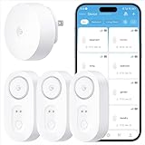
- Breakthrough 1804 ft Connectivity: Engineered with advanced Sub-1G long-range wireless tech, our leak detector maintains robust signals over unprecedented distances—reaching up to 1804 feet even through 5 dense walls. Secure every critical space in expansive properties, from deep basements to detached garages and distant outbuildings.
- Multiple Reminder Methods: Our water leak sensor supports multiple remote alarm. It can instantly send SMS, APP, and Email notifications to your phone (no matter how many times the SMS is used, it's free). Also, the water leak sensor flashes red and sounds a 105 dB alarm. Perfect for the basement, kitchen, or vacation home!
- Feature-Rich App: Receive instant push notifications. Use the “Find Device” feature to quickly trigger audible beeps to retrieve misplaced sensors. Add multiple email addresses through the APP, and your family and friends can also receive reminders when there is a water leak at home.
- Industry Leading IP67 Waterproof: Its IP67 waterproof rating ensures durability against spills, humidity, and accidental submersion.It can be used multiple times after wiping dry.
- Four-level volume adjustment: Customize your own alarm to fit your life! Use the app to adjust the volume in 4 levels, with a maximum alarm volume of 105 decibels. Whether it's day or night, whether it's in the bedroom or the basement, you can find the right volume.
Step 1: Record the observation before changing conditions
Capture the physical location
Mark the rack, row, CDU, manifold and loop involved. Photograph the area if your incident policy permits it, including nearby insulation, drip trays, cable paths and sensor identifiers. Record whether the moisture is above or below the suspected source. Gravity can carry leaked liquid away from the failed fitting, while condensation can form along an entire cold run.
Capture operating state
Write down pump state, flow rate, supply and return temperatures, pressure differential, valve positions, IT load and recent maintenance. A wet spot found immediately after a filter change or quick-disconnect operation needs a different investigation from one that appears only during humid weather. Preserve timestamps in the same time zone used by the BMS and CDU controller.
Step 2: Check telemetry, alarms and sensor coverage
Read the measurements that distinguish the causes
For non-CDU implementations, ASHRAE Technical Committee 9.9 specifically identifies supply-water temperature and server-inlet air dew point as useful telemetry. The white paper recommends connecting liquid-cooled equipment to the building-management system (BMS) so it can alarm when supply water approaches within 3.6°F (2°C) of incoming-air dew point. Read the original ASHRAE Water-Cooled Servers: Common Designs, Components, and Processes white paper for the design context; its publication is commonly dated approximately 2019, and the current PDF revision should be checked for the exact edition date.
- Room temperature, relative humidity and calculated dew point at the affected equipment.
- Server-inlet air dew point, not only a room average, because local airflow can create a different microclimate.
- Coolant supply temperature at the CDU outlet or facility-water connection, plus return temperature where available.
- Leak-sensor zone, alarm timestamp, latching state and communications path to the BMS.
- Flow, pressure differential, pump status and valve commands for the affected loop.
Check for blind spots
List which sections have rope, spot, tray or point sensors and which do not. A zone alarm reports that a sensor detected moisture; it does not prove that the nearest fitting failed. Conversely, condensation can occur on an unsensed surface. Compare the sensor map with the physical route of every hose and manifold, including low points where liquid can migrate.
Step 3: Compare coolant and surface temperature with dew point
Why dew point is the deciding reference
Relative humidity changes as air temperature changes, so it is not a sufficient safety limit by itself. Dew point is the temperature at which the air becomes saturated. If a pipe, cold plate connection or manifold surface reaches that temperature or below, water can condense from the air. Raising the surface temperature above dew point, reducing local humidity or improving insulation removes the condensation mechanism.
Rank #2

- Breakthrough 1804 ft Connectivity: Engineered with advanced Sub-1G long-range wireless tech, our leak detector maintains robust signals over unprecedented distances—reaching up to 1804 feet even through 5 dense walls. Secure every critical space in expansive properties, from deep basements to detached garages and distant outbuildings.
- Multiple Reminder Methods: Our water leak sensor supports multiple remote alarm. It can instantly send SMS, APP, and Email notifications to your phone (no matter how many times the SMS is used, it's free). Also, the water leak sensor flashes red and sounds a 105 dB alarm. Perfect for the basement, kitchen, or vacation home!
- Feature-Rich App: Receive instant push notifications. Use the “Find Device” feature to quickly trigger audible beeps to retrieve misplaced sensors. Add multiple email addresses through the APP, and your family and friends can also receive reminders when there is a water leak at home.
- Industry Leading IP67 Waterproof: Its IP67 waterproof rating ensures durability against spills, humidity, and accidental submersion.It can be used multiple times after wiping dry.
- Four-level volume adjustment: Customize your own alarm to fit your life! Use the app to adjust the volume in 4 levels, with a maximum alarm volume of 105 decibels. Whether it's day or night, whether it's in the bedroom or the basement, you can find the right volume.
ASHRAE’s handbook states: “One of the most important functions of the CDU, or whatever alternative distribution and control mechanism may be utilized, is to maintain coolant temperatures above the dew point.” This is a control objective, not permission to select a universal coolant setpoint without checking the equipment limits.
The non-CDU margin
For systems that couple facility water directly to the servers without a CDU, the ASHRAE Technical Committee 9.9 white paper recommends keeping facility water at least 3.6°F (2°C) above room ambient dew point. The paper describes this margin as a buffer for sensor uncertainty. It is guidance for non-CDU implementations, not a universal setpoint for every CDU, coolant or IT product. Follow the installed equipment’s specified minimum supply temperature, flow, pressure and water chemistry.
How to make the comparison
- Use a calibrated installed sensor where possible. A handheld temperature-and-humidity meter with dew-point calculation can provide a supplemental check, but it does not replace calibrated telemetry or BMS alarms.
- Measure air conditions at the server inlet or the actual cold surface, not only at a distant return-air sensor.
- Measure the surface or coolant temperature at the point where moisture is observed. Insulation, airflow and contact resistance can make a surface differ from the bulk fluid reading.
- Calculate the margin as coolant or surface temperature minus local dew point. A negative or near-zero margin indicates condensation risk; apply the equipment and site alarm limits rather than inventing a new threshold.
- Trend the margin through load changes and humid-weather conditions. A safe value at commissioning can become unsafe when chilled-water temperature, room humidity or airflow changes.
Step 4: Check for evidence of an actual fluid escape
Inspect without dismantling a live loop
Use the manufacturer’s inspection instructions for hoses, couplings, manifolds, cold plates, drains, expansion vessels and the CDU. Look for a continuing wet path, droplets emerging from a connection, damaged seals, an unexplained pressure decline, flow imbalance or a reservoir-level change. Do not loosen a fitting, remove a cold plate or open a drain merely to “see if it is leaking”; doing so can create the leak you are trying to diagnose.
Interpret alarms in context
Leak detection and intervention are separate functions. Eaton describes installing leak-detection systems and using temperature and humidity sensors to mitigate condensation risk in its vendor guidance and technical paper. Those statements describe Eaton’s products and practices, not independent certification of a particular installation. Read the Eaton CDU design guidance and Eaton CDU technical paper only in the context of the equipment actually installed.
A sensor alarm can be triggered by spilled water, cleaning fluid, condensation, cable damage or a sensor fault, depending on the technology. Confirm the zone, inspect the physical route and compare with pressure and flow trends. Treat a confirmed active leak as an incident even if the first alarm is ambiguous.
Rank #3

- Leaking & Dripping: 2 water sensitive probes on the front for monitoring pipe/drain drip and 4 rear probes for detection water leak & floor moisture/flood. Both are work simultaneously, whatever leak sensors contact water, it will warning you in time.
- Loud & Mute: Our water leak alarm have loud and Mute Mode. It can emit 100 dB audio and loud enough to be heard even if leaks happened in basement. Press the button to mute the Water Detector Alarm when you arrived the flooded place.
- Tiny & Wireless: No Wire, Installation Required. Mini size allows you to put water leak alarms on any places, where the water leak may be happened. Such as house, underground, Pool, under Washing Machine, or unexpected disasters that may burst pipes, etc..
- Ultra Lifespan: Due to built-in 2*AAA Battery and energy-efficient circuit, our Floor Water Sensor Moisture Alarm has over 2 years standby time with Low Battery Alert, which reminds you to replace battery in time via flashing red light.
- Real IP66 Waterproof: The Water Alarm Detector is made of ABS & Stainless Steel, helps water sensor keep sensibility during the long time used without rust. Mounting Battery from the front to protect battery from getting wet and safer.
What should I check when a CDU leak alarm goes off?
Use the approved response sequence
Immediately notify the people named in the facility incident plan and identify whether the alarm is active, latched or acknowledged. Verify the affected CDU, loop and sensor zone from the controller and BMS. If water or coolant is reaching electrical equipment, follow the site’s electrical safety and emergency power rules before approaching the area.
What’s actually slowing this PC down?
Pick the symptom - the matching free tool is one click away.
Vertiv’s Leak Detection and Intervention white paper discusses stopping flow at the CDU as one intervention consideration. That is an example of a response option, not a universal instruction. Some systems require branch isolation, controlled IT shutdown, redundant-loop transfer or another sequence to avoid equipment damage or thermal excursions.
Do not assume the sensor closes a valve
ASHRAE’s non-CDU guidance describes proportional valves that slow incoming water and binary valves that stop it, with alarms sent through the BMS. Whether those controls exist, what they control and whether they operate automatically depends on the design. Confirm command status and actual valve position; an alarm acknowledgement is not the same as hydraulic isolation.
When shutdown or isolation is uncertain
- Stop and call the designated facilities lead if the written procedure does not identify the correct valve or equipment state.
- Do not close a valve that could eliminate cooling for a healthy redundant path unless the sequence authorizes it.
- Do not restart pumps, open bypasses or reset alarms simply to clear the screen.
- Keep a time-stamped record of commands, valve positions, temperatures, pressures and personnel actions.
After stabilization: source investigation, repair and restart
Determine the failed mechanism
Once the loop is isolated or the equipment is safely shut down, inspect the suspected seal, coupling, hose, manifold, valve, drain, heat exchanger and sensor. Check whether condensation could have run into the sensor zone from an adjacent surface. Review maintenance records, installation torque requirements, hose bend radius, vibration, pressure spikes and water chemistry against the OEM limits.
Follow the system-specific service manual
There is no single industry-wide repair or restart checklist. Depending on the design, qualified service may require draining a secondary loop, replacing a seal or hose, refilling with a specified coolant, removing trapped air, checking conductivity or corrosion inhibitors, pressure-testing, verifying flow and confirming that all sensors and alarms operate. The sequence, fluid and acceptance limits must come from the installed system documentation.
Quick wins for a faster PC:
Clear out junk files and repair common Windows errorsFree Scan →Scan for outdated or missing drivers - takes under a minuteDriver Scan →Repair Windows errors before they cause bigger problemsFix Now →Rank #4

- Complete plug-and-play kit: hub plus Leak Sensor 4 units, each with a built-in 105 dB audible alarm for instant on-site alerts.
- Long-range LoRa: reliable coverage where Wi-Fi struggles (up to 2,034 feet open air); get app, email, and SMS/text alerts and name sensors by location.
- Works even without internet: with YoLink Control-D2D, sensors can directly trigger YoLink sirens or shutoff valves for local protection during outages.
- Low-maintenance power: each sensor uses 2 AAA batteries with up to 5 years typical battery life; easy replacement.
- Scalable IoT platform: one hub supports 300+ YoLink devices; part of a whole smart home/building ecosystem; hub options include standard Hub, SpeakerHub, and Cellular Hub.
Document the root cause, part numbers, fluid added or removed, test results, alarm behavior and the person who authorized return to service. Keep the incident record with the CDU and rack maintenance history so a recurring temperature margin or sensor-zone problem is visible.
How do I prevent condensation in liquid-cooled servers?
Control the dew-point margin
Maintain coolant above the local dew point with the CDU or alternative control mechanism, and apply the 2°C (3.6°F) facility-water margin where the ASHRAE non-CDU guidance applies. Use the equipment manufacturer’s operating envelope when it is more restrictive. Review the margin after changes to chilled-water temperature, room humidity, airflow, IT load, insulation or control software.
Measure both sides of the equation
- Install temperature and humidity sensors that can calculate dew point at representative server-inlet locations.
- Measure coolant supply temperature at the point relevant to the server or facility-water interface.
- Trend the temperature margin rather than looking only at instantaneous values.
- Alarm before the margin is consumed, using the site’s approved threshold and sensor-uncertainty allowance.
- Send alarms and trends to the BMS or equivalent supervisory system so facilities staff see them with other environmental conditions.
Manage cold surfaces and airflow
Inspect insulation continuity, vapor barriers, penetrations and clamps on any surface that can fall below room dew point. Avoid directing humid air across uninsulated cold pipes or manifolds. Check for local air mixing around racks; a room-average humidity value can hide a higher-dew-point pocket at a server inlet.
Specify compatible materials and fluid
ASHRAE notes that flow, pressure differential and water-quality requirements vary by equipment and cooling solution. Confirm coolant chemistry, materials compatibility, filtration, pressure limits and allowable flow with the OEM. A sensor or hose that is suitable for one loop may be unsuitable for another fluid or pressure class.
Do these 3 things before closing this tab:
1Clear out junk files and repair common Windows errors2Scan for outdated or missing drivers - takes under a minute3Repair Windows errors before they cause bigger problemsCDU and direct facility-water designs: what changes in troubleshooting?
| Decision axis | CDU-based system | Direct facility-water coupling (non-CDU) |
|---|---|---|
| Cooling-loop arrangement | Typically separates a technology-cooling loop from the facility loop and uses controls to manage coolant conditions. | Facility water is connected more directly to the liquid-cooled equipment, so facility-side temperature and quality management are critical. |
| Condensation control | Maintaining coolant above dew point is a core CDU control function; verify the installed CDU’s sensors and limits. | ASHRAE Technical Committee 9.9 recommends facility water at least 2°C above room ambient dew point. |
| Key telemetry | CDU supply/return temperature, flow, pressure, alarms, room dew point and leak zones. | Supply-water temperature and server-inlet air dew point are specifically recommended by ASHRAE, plus flow, pressure and leak-zone data. |
| Valve options | May include CDU or branch isolation and automatic intervention; verify the sequence of operations. | ASHRAE describes proportional valves to reduce incoming water and binary valves to stop it; confirm whether the installation implements them. |
| Service assumptions | CDU model, loop fluid, optional accessories and maintenance procedure are configuration-specific. | Facility-water treatment, pressure and water-quality requirements must match the IT equipment and site design. |
Use this table as a troubleshooting framework, not a substitute for the as-built drawings and operating procedure. Two systems described as “CDU” can still have different sensors, valves and isolation boundaries.
Best Value

- Never Miss a Leak: When a water leak is detected, a red light will flash on the water leak detector and the base station will sound an alarm up to 100 dB; you’ll also get an app alert on your phone, so you can learn about leaks even if you’re away
- Feature-Rich App: Adjust the base station alarm volume, mute an alarm, and view your alarm history via the app; tap “Remind Me Later” to temporarily mute the alerts for 10 minutes, 30 minutes, 2 hours, 6 hours or 12 hours; test the device, get low battery alerts, and share the sensor all from the app
- Top and Bottom Sensors: Featuring 2 ultra-sensitive water probes on the top and 4 on the bottom, this water leak sensor can sense water just 0.4 mm deep as well as drips from above, ensuring you're promptly alerted to any unexpected water without having to physically be there and check for yourself
- Ultra-Slim and Easy to Place: This water alarm fits into tight and awkward spaces thanks to its compact design; the device is only 0.7 in (17 mm) thick and 3 in (77 mm) in diameter
- Long Connection Range: Feel confident to put this sensor in an outbuilding or far away corner—its wireless connection range of up to 1,700 ft (500 m) in open areas means you’ll receive app alerts no matter where it’s placed
Leak detection equipment and monitoring choices
Installed sensor systems
For critical infrastructure, select rope, spot, tray or point sensors whose fluid compatibility, detection area, alarm outputs and environmental ratings match the installation. Integrate the controller with the BMS or incident platform, test alarm transmission and label every zone on the physical plan. A consumer-oriented “water leak detection sensor” may not provide the coverage, communications, fail-state behavior or maintenance controls required in a data center.
Supplemental temperature and humidity checks
A temperature-and-humidity meter with dew-point measurement is useful for commissioning checks, investigating a suspected cold spot or validating a fixed sensor. It is a supplemental instrument: it does not replace calibrated installed telemetry, trend retention or automatic BMS alarms.
System-specific options
HPE’s HPE Cray XD/ProLiant Direct Liquid Cooling System Site Preparation, User and Maintenance Guide identifies an optional leak-detection kit for the covered CDU systems. That demonstrates a configuration-specific accessory; it does not mean every HPE CDU includes the kit or that it fits another manufacturer’s system. Check the exact model and bill of materials.
Free tools Windows power users keep installed
One-click scans. No signup required.
Common troubleshooting mistakes
- Calling every wet spot a leak: First calculate the dew-point margin and inspect for a continuing escape.
- Using room relative humidity alone: Dew point at the server inlet or cold surface is the relevant comparison.
- Assuming a 2°C rule applies everywhere: The 3.6°F (2°C) margin is ASHRAE guidance for non-CDU implementations; it is not a universal setpoint for all CDUs or coolants.
- Resetting an alarm without preserving trends: Acknowledgement can erase the context needed to find an intermittent fault.
- Closing the nearest valve: Isolation boundaries and redundancy differ; use the approved sequence of operations.
- Dismantling a live connection: This can create a release, introduce air or contaminate the loop.
- Assuming a sensor stops the flow: Detection, alarm communication and hydraulic intervention are separate functions unless the design explicitly links them.
- Copying another installation’s fluid or pressure limits: Follow the installed OEM requirements for coolant, materials, flow, pressure and water quality.
What the published evidence does—and does not—establish
ASHRAE provides the dew-point principle and the 2°C non-CDU margin, along with recommended telemetry and example valve controls. Vendor documents add examples of leak monitoring and intervention, but they are not independent performance certification. Eaton reports “over 30.6 billion field hours with no leaks” in its liquid-cooling guidance; that is an Eaton vendor claim, with no independent audit or industry-wide applicability established in the cited material. It should not be used as a general leak-rate statistic.
No representative, independent industry-wide statistic for liquid-cooling leak frequency or condensation incidents is established by these sources. Operational decisions should therefore rely on the actual system design, calibrated measurements, alarm history, inspection findings and the site’s approved response procedure.
A practical incident record template
Use your facility’s approved form, but ensure it captures the information needed for engineering follow-up:
- Date and time, time zone and person discovering the condition.
- Room, row, rack, CDU, loop and leak-sensor zone.
- Surface temperature, coolant supply and return temperatures, room humidity, dew point and calculated margin.
- Flow, pressure, valve positions, pump state, IT load and relevant BMS/CDU alarm codes.
- Photographs or diagrams showing the moisture path and nearby sensors.
- Isolation, shutdown or transfer actions, with authorizations and timestamps.
- Inspection findings, replaced parts, fluid handling, pressure or leak tests and restart approval.
- Corrective actions such as insulation repair, sensor relocation, alarm-threshold review or procedure updates.
This record lets the next responder distinguish a recurring dew-point excursion from a mechanical failure and verify that corrective work addressed the cause rather than only the visible water.
Quick Recap
Product prices and availability are accurate as of the date/time indicated and are subject to change. Any price and availability information displayed on Amazon at the time of purchase will apply.

