Free tools Windows power users keep installed
One-click scans. No signup required.
Reduce errors in a photonic quantum circuit by treating loss as a measured budget, preserving photon indistinguishability and interferometer phase, and matching the detector chain to the encoding. First characterize every source of loss and noise; then fix coupling and propagation losses, stabilize phase and polarization, optimize detection, and compile shorter circuits. Near-term experiments can use zero-noise extrapolation or probabilistic error cancellation, while scalable machines need a loss-aware photonic error-correction code and decoder.
There is no universal photonic error threshold. A published number is meaningful only with its code, architecture, detector model and loss assumptions. The practical goal is therefore a closed, measured error budget that shows which improvement will most increase the probability of a correct result.

As an Amazon Associate I earn from qualifying purchases.
What “noise” means in a photonic quantum circuit
Photonic circuits carry information in properties such as path, polarization, time bin, frequency or a continuous optical quadrature. An error occurs whenever the photon state arriving at a gate, measurement or memory differs from the state assumed by the protocol. Some errors remove the photon; others leave it present but change its quantum state or make two photons distinguishable.
Crashes, No Sound, or Screen Glitches?
Random freezes, missing sound and display glitches usually trace back to one bad driver. Find and replace yours safely.Free scan · under a minuteWindows Errors? Fix Them Before They Spread
Repair common Windows errors and clear accumulated junk for a smoother, more stable PC - no reinstall needed.Free scan · no reinstallLoss and erasure
Loss is the most visible failure mode. A photon can be absorbed or scattered in a waveguide, lost at a bend, transmitted poorly by a coupler, blocked by a switch, or missed by a detector. In many photonic protocols a missing detection is an erasure that can be identified, but it still destroys the intended operation and consumes resources. Loss compounds across a circuit: if each required component transmits a fraction of the light, the probability that all components succeed falls multiplicatively with circuit depth.
#1 Best Overall

- [Ultra-Lightweight Ear Buds Designed for Small Ears] Each earbud weighs only 3.7g and features a compact, ergonomic in-ear design made especially for small ears. Secure, low-profile, and comfortable for workouts, all-day wear or overnight sleeping.The ultra-slim profile sits flush in your ear with no hard edges poking or rubbing, so you can even sleep on your side without discomfort.
- [Immersive Stereo Sound with TOZO OrigX Technology] TOZO OrigX tuning delivers clear vocals, balanced mids, and natural stereo sound for music, podcasts, and videos.
- [Long Battery Life for Daily Use] Get up to 7 hours of playtime on a single charge, with up to 32 hours total using the charging case—ideal for workdays, commuting, and extended listening sessions.
- [Bluetooth 5.3 & Stable Connection] Bluetooth 5.3 provides fast pairing, stable wireless performance, and reduced dropouts as you move around home or office.
- [Deep Bass with Clear Vocals] High-performance drivers produce punchy bass while keeping vocals clean and detailed for everyday listening.
Mode and timing errors
Two photons that are both present may not be identical. Differences in spectrum, arrival time, polarization or spatial mode reduce two-photon interference visibility. A fusion gate can then produce the wrong outcome even when no photon was absorbed. Mode mismatch at a fiber-chip interface is especially important because standard single-mode fiber has a mode-field diameter of about 10 micrometres, whereas silicon and silicon-nitride waveguides are submicrometre in scale.
Phase and polarization drift
Interferometers rely on stable relative phase. Temperature changes, mechanical vibration, stress in packaging and polarization rotation alter that phase or rotate the polarization basis. A circuit can therefore pass a static calibration and fail later without any change to its logical program.
Measurement noise
Detector inefficiency appears as additional loss. Dark counts create clicks when no photon arrived, timing jitter blurs which pulse or time bin was measured, and inadequate photon-number resolution can confuse a one-photon event with a multi-photon event. These effects change both the measured fidelity and the information supplied to an error decoder.
“For quantum computers to successfully solve real-world problems, it is necessary to tackle the challenge of noise: the errors that occur in elementary physical components due to unwanted or imperfect interactions.” — Zhenyu Cai and coauthors, Reviews of Modern Physics (2023)
Start with a measured error and loss budget
Do not optimize the component that is easiest to change. Establish a baseline for every stage from photon generation to final detection, using the same pulse rate, wavelength, polarization and operating temperature as the intended experiment.
Measurements to collect
- Source brightness: record usable photon rate, pair or multiphoton generation probability where relevant, and stability over the run.
- Indistinguishability: compare photon spectra, arrival-time distributions, polarization states and spatial modes. A two-photon interference measurement is useful only when its filtering and timing conditions are recorded.
- Propagation loss: measure each waveguide section, bend, crossing, switch and interferometer arm rather than only the complete chip.
- Interface loss: measure fiber-to-chip and chip-to-chip coupling separately, including alignment sensitivity and polarization dependence.
- Phase drift: log interferometer phase with a reference signal while temperature and mechanical conditions vary.
- Detector behavior: measure detection efficiency, dark-count rate, timing jitter, dead time and photon-number resolution for each channel.
- Readout correlations: determine whether detector channels share electrical or optical crosstalk, common timing errors or saturation.
Keep a loss ledger in decibels for optical transmission and a probability ledger for source, gate and detection success. Convert both to the probability of a complete event at the end of the circuit. A single aggregate number hides whether a redesign should target packaging, waveguides, switching or detectors.
Interpret a budget by location
| Location | Typical error mechanism | Useful diagnostic | First remedy to test |
|---|---|---|---|
| Source and filters | Low brightness, spectral impurity, timing spread | Single-photon spectra and arrival-time histograms | Improve filtering and synchronization without discarding more photons than the budget allows |
| Fiber-chip interface | Mode-field mismatch, alignment drift, polarization-dependent loss | Insertion-loss sweep versus lateral, vertical and angular alignment | Mode-matched or lensed coupling, inverse tapers, optimized edge couplers and stable packaging |
| Waveguides and bends | Scattering, absorption, radiation at tight bends | Cutback and component-level transmission measurements | Lower-loss waveguide geometry and larger-radius bends |
| Interferometer | Phase drift, imbalance, polarization rotation | Reference fringe visibility and phase-versus-temperature log | Integrated paths, thermal isolation, monitoring and closed-loop recalibration |
| Switches and reconfigurable elements | Insertion loss, imperfect extinction, drive noise | State-by-state transmission and extinction measurements | Use fewer active elements and schedule around the lowest-loss states |
| Detector chain | Missed photons, dark counts, timing jitter, unresolved photon number | Efficiency, dark-count, timing and number-resolution calibration | Choose detectors and gating matched to the encoding and decoder |
Close the optical-loss budget
Fix fiber-chip mode mismatch first
A standard fiber mode is roughly 10 micrometres across, while the guided mode in a silicon or silicon-nitride waveguide is submicrometre-scale. Directly joining the two creates substantial insertion loss and makes alignment fragile. Use an inverse taper to expand the on-chip mode, an edge coupler designed for the actual fiber, or a lensed and mode-matched interface. Measure coupling after the final package is assembled; a bare-chip alignment result does not establish packaged performance.
What’s actually slowing this PC down?
Pick the symptom - the matching free tool is one click away.
Rank #2

- 【IP68 Waterproof Multifunctinal Smart Watch】Torjalph fitness activity tracker smart watch is IP68 waterproof technology ,you can wear it when swimming,handwashing,it's rain-proof which means that you perform multiple exercise modes outside without worrying about sweat or rain corroding your fitness smart watch,and this watch equipped with a 230 mAh large capacity battery magnetic charging ,and this sports activity tracker watch can be used 5-7 days If fully charged.
- 【Larger 1.83'' Full Screen Watch & Multi-dial Selection】1.83 inch full HD color touch screen smart watch for men / women provides excellent 240*284 resolution image quality ,This Bluetooth smart watch offers a better touch experience and remarkable immersion and ,more than 200 watch faces for you to choose from App"Da Fit ", you can change the dial style according to your mood to wear keeping the world on your wrist
- 【Accurate Activity Tracker Smart Watch 】sports watch activity tracker uses sweat and dust resistant breathable silicone strap, our Fitness Tracker Smart Watch for Android iOS Phones supports 12 sports modes,walking,running,bicycle,swimming,badminton,basketball,football,rope skipping. This bluetooth calls smart watch for men women is lightweight and stylish, bringing more convenient and relaxing sports experience while also providing more protection.
- 【Your 24 Hour Personal Daily Health Monitor】Fitness watch for women men full touch screen IP67 waterproof bluetooth smartwatch for Android iOS Phones with heart rate blood pressure monitor multifunction Andriod smart watch with steps counter sleep monitor sports fitness watch, monitoring blood oxygen saturation allows you to understand your physical condition in real time to track fitness progress ,to know your health status in time.
- 【More Functions Bluetooth Call Smart Watch】This fitness activity smart watch full screen for iPhone and Android phones includes a bunch of new features including:The bluetooth smart watch can hang up the phone, receive and display WhatsAPP /Text /Facebook /Twitter /Messenger reminder.Support sedentary reminder, alarm clock, stopwatch, timer,weather information,music control, remote camera control compatible with Android 5.0 and above or iOS 9.0 and above smartphones.
Packaging must hold lateral, vertical and angular alignment through temperature changes and vibration. Record coupling loss for both polarizations if the circuit uses polarization encoding. A 2026 review of integrated photonics discusses inverse tapers, edge couplers and low-loss packaging as remedies for this mismatch. One reported silicon-nitride edge-coupler example achieved 0.5 dB insertion loss for two polarizations; that value belongs to that particular device and test, not to every edge coupler.
Reduce propagation and bend loss
Use waveguide material and geometry with measured low propagation loss at the operating wavelength. Replace unnecessarily tight bends with larger-radius routes, remove avoidable crossings, and keep long paths on the same thermal environment when they form an interferometer. Component-level cutback measurements distinguish distributed propagation loss from a single bad bend or interface.
Limit switches and mode changes
Every active switch adds insertion loss and may add state-dependent phase or polarization error. Compile the logical circuit so that modes are changed only when necessary, and route around a known lossy element when an equivalent path exists. If a switch is unavoidable, characterize each state and schedule the most photon-sensitive operations through its best state.
Account for packaging and connectors
Connectors, fiber arrays, chip-to-chip interfaces and protective windows belong in the same budget as the circuit itself. Clean and inspect facets, verify connector repeatability, and remeasure after thermal cycling. A design that meets its loss target on a probe station can miss it after adhesive, fiber-array and enclosure assembly.
Preserve indistinguishability, phase and polarization
Make photons arrive alike
Two-photon gates depend on overlap in every degree of freedom that the gate does not measure. Match spectral bandwidth and center frequency, equalize optical path delays, and use synchronized sources or active delay correction. Polarization controllers should be set with the complete packaged circuit in place, not only with a short test path. Spatial-mode mismatch at a coupler can undo an otherwise excellent spectral match.
When filtering improves indistinguishability, include the filter transmission in the brightness and loss budget. Narrow filtering can raise interference visibility while reducing the number of usable events; the correct setting is the one that improves the final logical success probability, not an isolated visibility number.
Stabilize interferometers
Integrate passive paths where possible so that relative phase is set by a compact, mechanically stable structure. Thermally isolate heaters and sensitive interferometer arms from one another. Place a reference optical signal on the chip or in a parallel monitor path, measure fringe phase continuously or at regular intervals, and use a feedback loop to correct drift. Recalibrate after a change in temperature, optical power, fiber position or mechanical mounting.
Rank #3
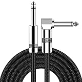
- [Low Noise High Fidelity] New bee guitar cord with 22AWG oxygen-free-copper center conductors provides enhanced signal transfer, the PVC insulation material and the high-density stranded copper double shield provide noise rejection for quiet operation
- [Ideal for Choice] New bee 1/4 straight and right angle metal connectors, ensures a secure connection in any instrument, pedal, or amp jack. L shape great fro on stage guitar stands
- [Wide Compatible] Suitable for mixer, power amplifier, microphone, effector, decoder, equalizer, electoronic organ, electric guitar, electric bass and other electronic equipments. Widely used in the installation of smart home, karaoke speaker, professional stage audio, etc
- [Easy Disassemble] Making incidental repairs quick and easy! Very nice, flexible cable
- [Dont Hesite to Order] 24 hours customer services and professional technology team are standing by
Calibrate phase and polarization together
Phase and polarization errors can be confused when only one output intensity is monitored. Use calibration states that exercise the relevant polarization and path combinations, then fit both phase and polarization parameters. Store calibration values with timestamps and environmental conditions so that a decoder or data-analysis pipeline can reject runs collected outside the valid range.
Integrated photonics has progressed toward compact, stable and programmable circuits, with reviews reporting platforms approaching 1,000 integrated components. More components make calibration and thermal crosstalk management more important, not less.
Design the detector chain around the encoding
Choose efficiency over a headline specification
High detection efficiency increases the probability that a photon is recorded, but a detector with a higher dark-count rate can create false syndromes. Compare total logical performance using the detector’s efficiency, dark counts, timing jitter, dead time and operating conditions. Include coupling into the detector and any filtering before it.
Match timing to the protocol
Synchronize detector gates and time-taggers to the source repetition rate and optical delay. Timing jitter must be small relative to the separation between time bins or the coincidence window used by the gate. Measure the full timing distribution, including electronics, rather than relying on the detector’s nominal value.
Use photon-number resolution when required
Some discrete-variable protocols and syndrome measurements distinguish one, two or more photons. Threshold detectors that report only “click” or “no click” can merge these outcomes and deprive the decoder of information. Use photon-number-resolving detection when the code or gate requires it, and characterize resolution at the photon-number range actually used. Continuous-variable and discrete-variable systems have different detector requirements; a detector suitable for one encoding is not automatically suitable for the other.
Control dark counts and crosstalk
Reduce stray light with shielding, spectral filtering and synchronized gating. Measure dark counts with the input blocked at the same temperature and gate settings used in data collection. Check electrical and optical crosstalk by firing neighboring channels separately and together. Feed measured false-click probabilities into the syndrome decoder instead of treating every detection as equally trustworthy.
Reduce exposure through circuit design and compilation
Even perfect components cannot rescue an unnecessarily long optical path. Compile the logical program to minimize circuit depth, active components, switches and mode changes. Cancel adjacent inverse operations, combine compatible interferometer settings, and reuse a calibrated path rather than opening a new route. Place loss-sensitive measurements before optional operations when the protocol permits it.
Rank #4

- Digital Family Calendar: BSIMB digital calendar wall touch screen puts an end to your chaotic life. Designed for busy families, the digital calendar keeps you organised and in step with your family. Assign different colours and tasks to each family member to make family scheduling easier and more intuitive.
- Easy Setup and Auto-Sync: Plug in, connect to WLAN and auto-syn your electric calendar in minutes. Digital wall calendar compatible with Google calendar, iCloud calendar, Outlook calendar, Cozi calendar and Yahoo calendar. Add events directly on the device or through the ecalendar app. Electronic calendar stays current whether you're at work or traveling—no manual updates needed.
- All-In-One Home Assistant: Smart calendar builds habits and encourage independence with personalised chores. Display daily meal plan to reduce the daily ‘What's for dinner?’ stress. To-do lists keep track of everything you want. Turning chores into valuable achievements with stars and rewards, making life easier and more enjoyable.
- Manage Anytime Anywhere: BSIMB electronic calendar for family stay connected with the powerful ecalendar app. Access and manage your digital wall calendar anytime, anywhere with free features like stars & rewards, photo screensaver, chore charts, meals plans, to-do lists etc. Electronic planner paid features like Magic Import tailor advanced tools for users with special needs.
- Stay in Touch with Loved Ones: Share photos or videos from your phone to electronic wall calendar with app, instantly update your life moment, and keep in touch with your family, especially those who are far away; you can also surprise your smart calendar digital wall by sending him a wish card; it's also great for keeping tech-illiterate elders in touch with the youngsters.
Error-aware scheduling
- Assign measured transmission and phase stability to each route in the circuit graph.
- Prefer the shortest and most stable route for photons that participate in a multi-photon interference event.
- Schedule calibration pulses during idle periods instead of interrupting a long data run.
- Avoid heating several neighboring phase shifters simultaneously when thermal crosstalk is significant.
- Record the actual switch states and calibration constants with every shot so that post-processing uses the correct noise model.
These changes do not correct an error after it occurs; they reduce the number of opportunities for one to occur and make the remaining errors easier to model.
Use error mitigation for near-term circuits
Error mitigation estimates what an ideal observable would have been without encoding every logical qubit in a fault-tolerant code. It is useful when a circuit is too small or too noisy for full correction, but it cannot restore a lost photon or provide indefinitely reliable computation.
The Tool Desk
Outbyte PC Repair FREEClear out junk files and repair common Windows errorsFree Scan →Outbyte Driver Updater FREEFix the driver behind crashes, sound loss and screen glitchesFind Drivers →Zero-noise extrapolation
Run an observable at several deliberately increased noise levels, for example by stretching pulse durations or inserting controlled repetitions that preserve the ideal operation, then extrapolate toward zero noise. The scaling operation must be validated for the optical device: increasing heater power, adding delay or repeating a component can change the noise mechanism rather than simply scale it. Report the extrapolation model, calibration range and statistical uncertainty.
Probabilistic error cancellation
Represent an ideal operation as a signed combination of noisy operations and sample that combination with calibrated probabilities. This can reduce bias when the noise model is accurate, but sampling overhead grows quickly and model errors can dominate. Estimate the model from independent calibration data, update it when phase or detector conditions drift, and publish the overhead required to reach the reported uncertainty.
What mitigation cannot do
Mitigation does not replace a loss-tolerant code, and it is not a license to quote a lower physical error rate than the detectors and sources actually provide. Report raw results, mitigated results, the noise-scaling procedure, the number of samples and confidence intervals together.
Independent reader supportYour contribution helps us test, update, and keep practical guides available for everyone.When to use photonic quantum error correction
Move from mitigation to quantum error correction (QEC) when the application needs circuit depth or reliability beyond what the physical loss budget supports. Photonic QEC treats loss, probabilistic gates and measurement outcomes as part of the code design rather than as exceptional faults.
Quick wins for a faster PC:
Repair Windows errors before they cause bigger problemsFix Now →Fix the driver behind crashes, sound loss and screen glitchesFind Drivers →Discrete-variable fusion-based schemes
Fusion-based architectures build large resource states from smaller photonic states and probabilistic fusion operations. Their correction model can use the fact that a missing photon is often detectable as an erasure. The code, resource-state factory, fusion success probability and detector model must be designed together. A Nature Communications study published in 2023 reported a ballistic scheme tolerating 10.4% loss per fusion, corresponding to 2.7% loss per individual photon under that architecture’s assumptions. Those figures are not universal limits for every fusion circuit.
Continuous-variable and GKP approaches
Continuous-variable systems encode information in optical quadratures; Gottesman–Kitaev–Preskill (GKP) states add a non-Gaussian structure that can support correction of small displacement errors. They require appropriate non-Gaussian resource generation, homodyne or related measurements, phase-stable optics and a decoder suited to analog outcomes. Their source and detector requirements differ from few-photon fusion systems, so a direct comparison based only on detector efficiency or source brightness is misleading.
Compare architectures by the complete stack
| Criterion | Discrete-variable fusion circuits | Continuous-variable/GKP circuits |
|---|---|---|
| Primary loss model | Photon loss and probabilistic fusion outcomes are explicit erasures or located failures | Optical loss combines with quadrature noise and finite-quality non-Gaussian states |
| Source requirement | Many schemes rely on few-photon resource states; source determinism and state-factory overhead matter | Requires high-quality squeezed states and non-Gaussian resources; deterministic preparation is challenging |
| Detector requirement | Often needs efficient click detection; some syndromes require photon-number resolution | Homodyne-style measurements provide analog information, with phase stability and calibration requirements |
| Phase sensitivity | Interference visibility and path phase determine fusion success | Quadrature reference phase and squeezing alignment are critical |
| Resource overhead | Resource-state generation and failed fusions consume photons and time | State preparation and non-Gaussian operations add optical and computational overhead |
| Decoder complexity | Uses discrete outcomes plus erasure information; speed must match the fusion cycle | Processes analog measurement values and a noise model for displacement and loss |
| Fabrication maturity | Integrated sources, interferometers and detectors are active development areas | Integrated squeezing and non-Gaussian components remain active development areas |
A Nature architecture review published in 2025 noted that no complete photonic architecture had yet been experimentally demonstrated at any scale, despite progress in many building blocks. Treat architecture-level claims accordingly: a high-performing source, coupler or detector is not evidence that a complete fault-tolerant machine has been demonstrated.
Build a loss-aware QEC and decoding loop
- Specify the code and architecture. Name the photonic encoding, resource-state construction, fusion pattern or GKP lattice, detector model and assumed noise channels.
- Map physical events to syndromes. Distinguish a no-click erasure, a dark-count click, an ambiguous photon number and a valid detection. Preserve analog confidence information when the code supports it.
- Measure parameters in situ. Re-estimate transmission, dark counts, timing jitter, phase drift and source quality during the same operating cycle as computation.
- Choose a decoder with bounded latency. A decoder that returns after the next fusion or measurement cycle is required for feed-forward; offline decoding is insufficient for a time-critical protocol.
- Validate below the code’s modeled threshold. Thresholds depend on code, architecture and noise model. Do not transfer a threshold from one paper to a different layout or detector assumption.
- Track overhead. Report photons, modes, detectors, resource states, repetitions and classical processing required per logical operation.
Troubleshoot by symptom
| Symptom | Likely causes | Checks and corrective action |
|---|---|---|
| Coincidence visibility falls after packaging | Mode mismatch, polarization rotation or path delay change | Re-map fiber alignment, inspect polarization-dependent loss, measure spectra and arrival times, then recalibrate with the final package installed |
| Counts decline uniformly across outputs | New interface loss, dirty facet, damaged fiber or detector efficiency change | Use a calibrated reference source, measure each interface separately and compare detector efficiency with the previous calibration |
| One interferometer output drifts while total power is stable | Relative phase drift or thermal crosstalk | Monitor a reference fringe, isolate heaters, increase thermal control and close a phase-feedback loop |
| False syndromes increase with no source change | Dark counts, stray light, electrical crosstalk or timing-window misalignment | Run blocked-input dark-count tests, inspect shielding, fire channels independently and retune gate timing |
| Mitigated values vary wildly between runs | Noise model no longer matches the circuit or extrapolation range is too large | Recalibrate, narrow the noise-scaling range, increase samples and report confidence intervals |
| Decoder fails at expected loss | Threshold borrowed from another code, unmodeled correlations or missing detector information | Reproduce the exact code and architecture model, include correlated and measurement errors, and preserve erasure and photon-number data |
How to report a credible noise result
- State the wavelength, encoding, chip material, temperature and packaging configuration.
- Separate source, coupling, propagation, switching and detector losses.
- Give detector efficiency, dark counts, timing jitter and photon-number capability under the data-collection settings.
- Report phase-drift rate, calibration interval and environmental conditions.
- Identify whether a number is a component measurement, a full-circuit result, a one-time allowance or a model assumption.
- For QEC, name the code, architecture, decoder, noise model and threshold definition.
- For mitigation, publish raw and corrected observables, calibration data, sampling overhead and uncertainty.
These details let another team determine whether an improvement came from lower physical loss, better indistinguishability, cleaner measurement or a change in analysis.
Do these 3 things before closing this tab:
1Repair Windows errors before they cause bigger problems2Scan for outdated or missing drivers - takes under a minute3Clear out junk files and repair common Windows errorsA practical sequence for reducing errors
- Characterize first: measure source brightness and indistinguishability; component, coupling and detector losses; phase drift; polarization stability; dark counts; timing jitter; and number resolution.
- Close the largest loss term: replace lossy bends or interfaces, apply mode-matched or lensed coupling, use inverse tapers or optimized edge couplers, and stabilize packaging.
- Stabilize the optical network: integrate passive paths, thermally isolate sensitive elements, monitor a reference and recalibrate phase and polarization after environmental changes.
- Improve readout: select detectors with the efficiency, dark-noise, timing and number-resolution characteristics required by the encoding; synchronize gates and time tags.
- Shorten the exposure: compile for fewer components, switches, mode changes and optical delays; schedule around measured low-loss routes.
- Apply mitigation with evidence: fit a noise model to calibration data, choose zero-noise extrapolation or probabilistic cancellation only when its assumptions fit, and report uncertainty and sampling cost.
- Adopt QEC for scale: select a loss-tailored code, design syndrome extraction around available detectors, and use a decoder fast enough for the code cycle.
The most reliable strategy is not a single “low-noise” component. It is a controlled loop in which optical loss, indistinguishability, phase, detector behavior and decoding assumptions are measured together and improved in the order that most increases complete logical-event probability.
Frequently Asked Questions
What is usually the first loss to fix in a photonic circuit?
Measure the complete budget first, but fiber-chip coupling is often a high-leverage target because the roughly 10-micrometre mode of standard single-mode fiber must be matched to a submicrometre silicon or silicon-nitride waveguide mode. Inverse tapers, optimized edge couplers, lensed coupling and stable packaging address that mismatch.
Can zero-noise extrapolation make a photonic circuit fault tolerant?
No. It can reduce bias in selected observables when the noise-scaling model is accurate, but it does not recover lost photons or provide the scalable protection of a loss-aware quantum error-correction code.
Is the 10.4% photonic loss threshold universal?
No. The 10.4% loss-per-fusion figure, equivalent to 2.7% per individual photon in the cited 2023 ballistic scheme, applies to that code, architecture and noise assumptions. Thresholds must not be transferred to another photonic design without re-analysis.
Which detector should a photonic quantum computer use?
The choice follows the encoding and syndrome measurement. Compare efficiency, dark counts, timing jitter, dead time and photon-number capability; discrete-variable circuits may require number resolution, while continuous-variable systems need phase-stable analog measurements.
Quick Recap
Product prices and availability are accurate as of the date/time indicated and are subject to change. Any price and availability information displayed on Amazon at the time of purchase will apply.

