The Tool Desk
Outbyte Driver Updater FREEScan for outdated or missing drivers - takes under a minuteDriver Scan →Outbyte PC Repair FREERepair Windows errors before they cause bigger problemsFix Now →The reliable way to size solar power for a Meshtastic node is to measure the exact node you will deploy, convert that measurement to watt-hours per day, then size the battery and panel for your worst weather—not from a single current reading or a panel’s headline wattage.
Measure for at least an hour, preferably two to six hours, and use a full-day run for final sizing. A node measured at 0.24 W average uses about 5.8 Wh per day. The battery must cover your planned sunless days after depth-of-discharge, temperature, ageing and conversion losses; the panel must run the node and replenish that energy after cloudy periods.
As an Amazon Associate I earn from qualifying purchases.
Why there is no universal solar size for a mesh node
Two nodes running the same firmware can have very different energy budgets. Board family, modem preset, traffic, router behavior, GPS, sensors, display use, Wi-Fi or Bluetooth, antenna hardware, supply voltage and local weather all change the result. A lightly used sensor node may consume a fraction of the energy required by a busy router relaying traffic all day.
Meshtastic’s official guidance states: “Measure the node’s energy use before choosing a solar panel and battery.” That is the essential design rule. Published panel ratings and nominal battery capacities describe components, not the autonomy of a complete installation. Shading, winter sun, controller efficiency, wiring resistance, cold temperatures and the battery’s usable capacity determine what the node actually receives.
#1 Best Overall
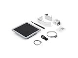
- Solar Powered & Low Maintenance – Equipped with a built-in solar panel and rechargeable battery, the SenseCAP P1-Pro ensures continuous power supply for long-term outdoor use without frequent charging. Perfect for off-grid and remote deployments
- Long Range LoRa & Meshtastic Compatibility – Designed for seamless integration with the open-source Meshtastic project, providing reliable long-range wireless communication using LoRa technology. Ideal for outdoor adventures, hiking, or remote area networking
- GPS Tracking & Outdoor Ready – Features integrated GPS for accurate location tracking. With its weatherproof enclosure, it’s built to withstand outdoor environments, ensuring durability in diverse conditions
- Powered by XIAO nRF52840 Plus – Built around the Nordic nRF52840 SoC with a 32-bit ARM Cortex-M4F core, Bluetooth 5.0, low-power performance, and reliable support for Meshtastic-based outdoor mesh communication
- Flexible for IoT Applications – Ideal for hobbyists, educators, and professionals. Can be customized for IoT sensor networks, emergency communication, outdoor exploration, and educational projects. Backed by Seeed Studio’s OEM/ODM expertise for scalable solutions
Use the following sequence:
- Build the node with the board, antenna, modem preset, GPS, sensors, role and power settings you intend to install.
- Measure accumulated energy or charge while it performs representative work.
- Convert the result to average watts and daily watt-hours.
- Choose how many sunless days the battery must cover.
- Calculate panel and battery capacity with losses and a recovery margin.
- Install, then use telemetry to confirm that the battery regularly reaches a healthy charge state.
Measure the node’s real energy use
Why an instantaneous current reading is inadequate
A Meshtastic node does not draw a constant current. Receive, standby, transmit, GPS acquisition, sensor sampling and wireless configuration create different loads. A handheld multimeter showing one momentary value can catch any one of those states and miss the others. Sizing from that number can leave the panel too small or the battery unnecessarily large.
Use a watt-hour power meter, an energy-logging supply, or a meter that records amp-hours over time. If your instrument reports only amp-hours, record the voltage at the node as well so you can convert charge to energy. The measurement must be taken at the node’s actual operating voltage, after any regulator or converter that will remain in the final installation.
Run a representative test
- Install the final firmware and configure the intended region, modem preset, channel settings, role, GPS and sensors.
- Connect the node through an energy meter. Include the regulator, USB cable or DC wiring that will be used in the field; losses in those parts belong in the measurement.
- Leave the node in its normal enclosure and antenna arrangement. Keep Wi-Fi, Bluetooth and a display enabled if they will be enabled outdoors.
- Generate normal traffic. A router should relay the sort of traffic expected at the site; a sensor node should take readings at its real interval. Avoid sizing from an idle bench period.
- Record accumulated watt-hours for at least one hour. Two to six hours gives a more useful average, and a complete day captures duty cycles such as GPS fixes or scheduled sensor activity.
- Repeat after changing a major setting. For example, measure once with a GPS enabled and again with it disabled rather than assuming the difference.
Short tests are useful for comparing settings, but the final design should represent the traffic and environmental schedule of the deployed node. If traffic is seasonal or event-driven, test the busiest credible pattern or size separate operating profiles.
Convert the measurement to daily watt-hours
The basic equations
Power is measured in watts (W); energy is power accumulated over time and is measured in watt-hours (Wh). Calculate the average power first:
average watts = measured watt-hours ÷ test hours
Then calculate daily energy:
daily Wh = average watts × 24
If the meter reports amp-hours instead, use:
watt-hours = amp-hours × average operating volts
Use the voltage at the node, not necessarily the panel’s open-circuit voltage or the battery’s nominal label. A regulator can change both voltage and current, and the conversion loss is best captured by measuring downstream of that regulator.
Official examples
Meshtastic’s worked example uses 5 V and 50 mA: 5 V × 0.05 A = 0.25 W, or 250 mW. Running continuously for 24 hours gives 0.25 W × 24 h = 6 Wh per day.
Another example records an average of 241.4 mW. Multiplying 0.2414 W by 24 hours gives approximately 5.8 Wh per day. These are examples, not a universal consumption benchmark for every board or configuration.
Keep a measurement log
Write down the board, firmware version, role, modem preset, supply voltage, antenna, GPS and sensor state, test dates, traffic pattern, test duration and meter placement. Record both the accumulated energy and any unusual event, such as a firmware update or prolonged Bluetooth session. This log makes later changes diagnosable and lets you re-size the system when the node’s role changes.
Choose battery capacity from autonomy
Set the autonomy target
Autonomy is the number of days the node must operate without useful solar input. Choose it from the installation, not from a product label. A hilltop repeater in a cloudy winter location may need more reserve than a backyard sensor with easy access for charging. Define the target explicitly—for example, several sunless days—and use the longest plausible cloudy interval for the season that matters.
Use usable energy, not nominal label capacity
A battery’s printed watt-hours are not all available to the node. Reserve energy may be kept to avoid excessive depth of discharge (DoD), cold can reduce capacity, ageing lowers capacity over time, and a DC converter consumes energy. Size nominal battery energy with a margin for each factor:
nominal battery Wh = daily Wh × autonomy days ÷ (usable DoD × temperature factor × ageing factor × conversion efficiency)
Windows Errors? Fix Them Before They Spread
Repair common Windows errors and clear accumulated junk for a smoother, more stable PC - no reinstall needed.Free scan · no reinstallOutdated Drivers Are Slowing You Down
One free scan finds every outdated or missing driver and matches the right update for your exact hardware.Free scan · exact hardware matchRank #2

- Multi-protocol support: Featuring nRF52840 and LR1110, it supports LoRa (global ISM bands in the 863-928 MHz range). After purchasing the T1000-E, you can freely choose your region in the Meshtastic app. It also supports Bluetooth 5.0, Thread, and Zigbee, ensuring compatibility with a wide range of devices and networks.
- Powerful Positioning Capabilities: Integrated with the Mediatek‘s AG3335 GPS chip, it provides high-precision positioning services.
- Expandable Interfaces: Designed with four pogo pins, it supports USB interface for DFU (Device Firmware Upgrade), serial logging, and API interface, simplifying device management and debugging.
- Open Source Support: Compatible with the Meshtastic open-source mesh networking protocol, suitable for long-range and low-power communication needs.
The factors are design assumptions that must match your battery chemistry, controller and climate. If a battery specification gives a usable-energy figure, use that figure instead of applying DoD twice. Keep the calculation in watt-hours until the end; convert to amp-hours only after selecting the battery voltage:
amp-hours = required watt-hours ÷ nominal battery volts
Example calculation
Assume a measured 5.8 Wh/day load, three sunless days, 80% usable DoD, 85% conversion efficiency, and a combined 80% allowance for cold and ageing. The illustrative requirement is 5.8 × 3 ÷ (0.8 × 0.85 × 0.8), or about 32 Wh of nominal storage. At a nominal 3.7 V, that is roughly 8.6 Ah. Those factors are example assumptions, not a claim about a particular cell or climate; substitute the limits in your battery and controller documentation.
Battery chemistry and safety decisions
- Match the solar charge controller to the battery chemistry, nominal voltage and charging limits. A controller designed for one chemistry is not automatically safe for another.
- Use cells with a protection system or battery-management system appropriate to the pack. Do not mix cells of different age, capacity or condition.
- Respect the manufacturer’s low-temperature charging limits. A battery can require protection from charging below its specified temperature.
- Provide a fuse or other over-current protection close to the battery, use correctly rated conductors, and insulate exposed terminals.
- Do not infer pack capacity by simply adding every cell’s printed milliamp-hour number unless the series/parallel arrangement and usable voltage range are understood.
Size the solar panel for daily load and bad weather
Peak-sun-hour method
Estimate the installation’s worst-month peak-sun hours (PSH), not the longest summer day. Then calculate the minimum panel rating:
panel watts ≥ daily Wh ÷ (PSH × total system efficiency)
Total system efficiency includes the charge controller, wiring, battery charging and voltage conversion. Add a recovery margin so the panel can operate the node and refill the battery after cloudy weather. The margin should reflect shading, snow or dust, seasonal uncertainty and how quickly you need the battery to recover; there is no single valid percentage for every site.
Illustrative panel calculation
For the 5.8 Wh/day example, assume four peak-sun hours and 70% total system efficiency. The calculated minimum is 5.8 ÷ (4 × 0.70), or about 2.1 W. A designer might then select a larger panel to provide recovery margin and tolerate partial shade. Choosing a 5 W panel in this example is a design decision based on those assumptions, not proof that every 5 W installation will run a node year-round.
Check panel and controller compatibility
- Verify the panel’s operating voltage and current are within the controller’s input range in both bright and cold conditions.
- Confirm the controller can charge the selected battery chemistry and voltage, and that its maximum current is adequate for the panel.
- Include the node’s regulator in the power budget. A panel cannot charge a battery safely by connecting it directly to a node or cell.
- Allow for voltage drop in long or thin cables. Measure at the controller and at the node under load.
Reduce consumption before buying more hardware
Choose an efficient board
Meshtastic identifies nRF52 hardware as more power efficient than ESP32 hardware and suitable for battery and solar deployments. This is a platform-level guideline; the exact board, peripherals and firmware settings still need measurement.
Quick wins for a faster PC:
Scan for outdated or missing drivers - takes under a minuteDriver Scan →Repair Windows errors before they cause bigger problemsFix Now →Use the appropriate role
A ROUTER role enables power-saving behavior, shuts down Wi-Fi and Bluetooth, and leaves the LoRa receiver on standby. That can be appropriate for a permanently installed relay, but it changes how the node behaves and should be validated against your coverage and management needs. If you need local configuration or frequent Bluetooth access, measure that operating mode instead of assuming router consumption.
Audit every peripheral
- GPS receivers can draw significant energy while acquiring and tracking satellites; use the required fix interval rather than leaving continuous tracking enabled by habit.
- Sensors, displays, status LEDs and environmental heaters add loads that may dominate a low-power radio.
- Wi-Fi and Bluetooth should be disabled when their functions are not required in the field.
- Choose a modem preset and telemetry interval that meet the coverage requirement without creating unnecessary traffic.
Packaged solar-node options
Integrated products can simplify enclosure, wiring and battery mounting, but their nominal specifications do not establish autonomy for your site. Confirm what is included and whether cells are replaceable before comparing prices or capacity.
| Option | Published hardware details | Battery included? | What to verify |
|---|---|---|---|
| Seeed SenseCAP Solar Node P1 | Integrated 5 W panel and four 18650 slots | Four 3350 mAh cells are included with P1 Pro; P1 requires user-supplied cells | Cell quality and matching, charge-controller limits, measured load and real winter autonomy |
| Elecrow ThinkNode M6 | 6 W panel, two 18650 cells and an IP65 outdoor enclosure | Two cells are part of the stated package | Usable battery energy, replacement-cell procedure, cable routing and local shading |
| RAK WisMesh Repeater models | Optional high-capacity batteries and external-panel support | Depends on the selected model and option | Exact battery option, controller compatibility, connector ratings and enclosure installation |
“Four 18650 slots” is not the same as a guaranteed four-cell capacity: the cells, series/parallel arrangement, protection circuit and usable DoD determine available energy. Likewise, a 5 W or 6 W panel rating is measured under specified test conditions and will be lower in shade, poor orientation or weak winter sun.
Rank #3

- Ultimate IoT development kit: The Ultimate IoT Development Kit: The D5L-H1 is a newly developed IoT device—a LoRa node—that integrates solar power and a LoRa chip. It's an extremely cost-effective device that can function as a repeater for seamless autonomous operation. Easily tether to your phone via Bluetooth, update settings, and connect to Meshtastic LoRa devices.
- Powerful chipset: The ESP32 LoRa V3 development board combines an ESP32-S3 microprocessor with an SX1262 LoRa chip, making it ideal for IoT applications, smart cities, and agricultural solutions. Thanks to integrated Wi-Fi, Bluetooth, and LoRa connectivity, this device is a true powerhouse for any maker and developer.
- Perfect design for long-distance communication: Perfect for remote campsites, hiking expeditions, emergency networks, and off-grid installations, the relay station supports seamless communication over long distances.Suitable for wireless data transmission and device control with industrial standard or non-standard user protocols.
- Solar-Powered & Autonomous Operation: Fully powered by a 5W solar panel and 2pcs LiPo batteries, the D5L-H1 Relay operates autonomously, ensuring continuous off-grid communication without the need for external power sources
- Long-Range Connectivity: Supports point-to-point, point-to-multipoint, relay network, AES, etc, Compact size, easy to install.Extends communication coverage up to 1-3 km in urban areas and 3-10 km in rural environments, depending on mounting height and line of sight
Build the power path safely
The normal architecture is:
solar panel → solar charge controller → protected battery → regulated output → Meshtastic node
Recommended Free Tools
Keep the controller and battery protected from water, condensation and temperature extremes while giving the panel clear exposure. Use weather-resistant cable glands, strain relief and connectors rated for outdoor use. Route conductors so water cannot run directly into the enclosure, and leave service access for replacing a fuse or cell pack.
Battery and controller checks
- Confirm polarity before connecting the panel, battery and load. Reverse polarity can destroy a controller or node.
- Check the controller’s low-voltage cutoff so the node is not repeatedly driven into an unsafe battery state.
- Ensure the controller can supply the node’s startup current as well as its measured average.
- Keep the battery’s protection system accessible for inspection without exposing live terminals.
- Ground or bond components only as required by their instructions; do not create an unintended path through the radio or antenna system.
Installation procedure
- Freeze the configuration. Record the board, firmware, antenna, role, modem preset, GPS, sensors and telemetry interval.
- Measure energy. Log watt-hours for the representative test period, preferably a full day, and calculate average watts and daily Wh.
- Set autonomy. Choose the number of sunless days and document DoD, temperature, ageing and conversion assumptions.
- Calculate storage. Use the battery equation, then select a chemistry-compatible pack with protection and enough nominal Wh.
- Estimate solar input. Use worst-month PSH and measured system efficiency, then add a recovery margin for weather and shading.
- Validate components. Check panel voltage, controller input and charging limits, battery voltage, fuse rating, regulator output and cable gauge.
- Mount the panel. Keep it clear of shadows from poles, branches and the enclosure during the useful part of the day. Account for seasonal sun angle.
- Install the battery and controller. Seal the enclosure, provide ventilation or thermal protection where required, add strain relief and place over-current protection near the battery.
- Connect and inspect. Follow the controller’s prescribed connection order, verify polarity with a meter, and check the regulated node voltage before attaching the radio.
- Observe a complete weather cycle. Use telemetry and local measurements to confirm charging, overnight operation and recovery after cloudy periods.
Use telemetry to prove the design
Meshtastic telemetry exposes battery level and current or power-consumption fields. Log those values over time rather than checking one percentage after installation. A healthy system should show the battery declining overnight or during poor weather, then reaching a high charge state when solar input returns.
What to watch
- Battery percentage or voltage at the same point in the daily cycle.
- Charge current during clear midday conditions and load current when the radio transmits.
- Whether the battery reaches its charge target before the next night.
- How many cloudy days pass before the low-voltage cutoff or node reset occurs.
- Unexpected increases after enabling GPS, sensors, Bluetooth, Wi-Fi or a busier modem preset.
Telemetry is a diagnostic signal, not a laboratory calibration. Compare trends with a known meter during commissioning, and treat an implausibly stable percentage or sudden voltage collapse as a reason to inspect the sensor, wiring, battery and controller.
Troubleshoot common failures
The node resets overnight
Measure the battery voltage at the node while the radio transmits, not only at the battery terminals. A weak or undersized regulator, cable drop, excessive DoD, cold-related capacity loss or a failing cell can cause the voltage to dip. Reduce the load temporarily, shorten or thicken the cable, inspect connectors and check the controller’s cutoff settings.
The battery never reaches a full charge
Look for panel shading, incorrect orientation, dirty glass, a loose connector or a controller configured for the wrong chemistry. Compare midday panel voltage and controller charge current with the controller’s expected range. If the node’s daily Wh was underestimated, the panel may be running the load but never have surplus energy to refill the battery.
The system works in summer but fails in winter
Recalculate with winter PSH, longer cloudy intervals, lower temperatures and the battery’s cold-charge limits. A summer measurement is still useful for the node load, but it does not establish winter solar availability. Increase panel recovery capability, storage, or both, and remove seasonal shade where possible.
Telemetry reports unexpectedly high consumption
Check for a changed role, modem preset, GPS schedule, sensor polling interval or wireless configuration session. Measure the node again after disabling one peripheral at a time. Also inspect the regulator: an inefficient converter can add more energy use than the radio board itself.
Three design examples
Low-duty sensor node
Suppose measurement shows 0.05 W average. Daily energy is 0.05 × 24 = 1.2 Wh. For a three-day autonomy target, the battery must provide at least 3.6 Wh of usable energy before adding DoD, temperature, ageing and conversion allowances. Panel sizing still uses the site’s worst-month PSH and controller efficiency; the low load does not eliminate cloudy-weather margin.
Free tools Windows power users keep installed
One-click scans. No signup required.
Measured 5.8 Wh/day node
Using the official-style 5.8 Wh/day example, four PSH and 70% total efficiency produce a 2.1 W calculated minimum. A larger panel may be justified to recover the battery after cloudy days or tolerate partial shade. Battery capacity is calculated independently from the chosen autonomy and derating factors; panel wattage cannot substitute for insufficient storage overnight.
Busy repeater
A repeater should be measured while relaying representative traffic, including the busiest expected period. If its average rises from 0.24 W to 0.40 W after deployment, daily energy rises from about 5.8 Wh to 9.6 Wh. Both the battery and panel must be re-sized from the new measurement; changing only the panel leaves the night-time reserve unchanged.
Commissioning checklist
- Measured accumulated Wh or Ah over a representative period.
- Calculated average watts and daily Wh from the final configuration.
- Selected an explicit sunless-day autonomy target.
- Applied usable DoD, temperature, ageing and conversion allowances.
- Used worst-month PSH and total system efficiency for panel sizing.
- Added a documented recovery margin for clouds and shade.
- Matched controller settings to battery chemistry and voltage.
- Installed fuse protection, weather sealing, strain relief and correctly rated wiring.
- Confirmed panel and battery polarity before connecting the node.
- Enabled telemetry and recorded charge, discharge and low-voltage behavior over time.
Bottom line
Start with a full-day energy measurement of the exact Meshtastic configuration. Convert it to Wh/day, size the battery for your required sunless days after derating, and size the panel from worst-month sun hours plus enough margin to recover. Efficient hardware, a ROUTER power profile where appropriate, careful controller matching and telemetry-based commissioning matter more than choosing a panel from its nominal wattage alone.
Quick Recap
Product prices and availability are accurate as of the date/time indicated and are subject to change. Any price and availability information displayed on Amazon at the time of purchase will apply.
What’s actually slowing this PC down?
Pick the symptom - the matching free tool is one click away.

