Recommended Free Tools
Integrate a brownfield mineral-processing plant by first inventorying every instrument, controller, network boundary and data dependency; then define the exact operational decision each new signal must support. In most plants, the least disruptive path is to read useful data through an existing native protocol or a parallel edge layer while leaving proven control logic in place. A PLC, DCS or SCADA migration is justified when equipment is obsolete, unsupported, unsafe to maintain, or too fragmented to support the required function. Commission the connection in a bounded pilot, keep monitoring paths separate from control writes, and schedule any intrusive work inside an agreed outage window.
What integration means in a brownfield processing plant
A mineral-processing plant rarely has one uniform automation platform. The installed estate may include field transmitters and analyzers, motor starters, variable-frequency drives (VFDs), OEM skids, programmable logic controllers (PLCs), remote terminal units (RTUs), distributed control systems (DCS), safety systems, plantwide SCADA, operator HMIs and one or more historians. Grinding, flotation, thickening, conveying, pumping and water-treatment areas may have been expanded by different projects and vendors over many years.

As an Amazon Associate I earn from qualifying purchases.
Integration is therefore more than wiring a new sensor to a gateway. It is the controlled exposure of trustworthy measurements, commands and status from that heterogeneous estate to the people and applications that need them. The destination might be an operator alarm, a trend on a historian, a maintenance work order, a process-optimization model or, only after additional engineering, an advanced-control input.
Beckhoff describes the objective as using open interfaces and standardized communication protocols to integrate existing sensors and control systems without replacing an entire plant. AusIMM’s July–August 2023 discussion of the “digital edge” describes edge controllers installed in parallel with existing automation so selected information can be obtained from legacy hardware and newer IIoT devices. Those are architecture patterns, not guarantees that any unnamed controller or instrument will interoperate without a compatibility check.
#1 Best Overall

- INDUSTRIAL VIBRATION METER – VM-424 WITH REMOTE SENSOR PROBE - Designed for vibration measurement on motors, pumps, compressors, gearboxes, fans and rotating machinery where direct placement of a handheld meter is difficult. The external sensor allows technicians to reach narrow measurement points while keeping the main unit at a safe and comfortable viewing position.
- 3-IN-1 VIBRATION MEASUREMENT – ACCELERATION VELOCITY DISPLACEMENT - Measures Acceleration 0.1–199.9 m/s² (peak), Velocity 0.1–199.9 mm/s (RMS) and Displacement 0.001–1.999 mm (p-p), enabling technicians to evaluate key vibration parameters used in machine condition monitoring and preventive maintenance inspections.
- DUAL FREQUENCY ACCELERATION MODES – 10HZ–1KHZ AND 1KHZ–3KHZ - Low frequency mode supports general machine vibration evaluation such as imbalance or structural vibration, while high frequency mode helps observe higher-frequency vibration components during mechanical diagnostics.
- REMOTE PIEZOELECTRIC SENSOR – STABLE CONTACT MEASUREMENT - External shear-type accelerometer connected by cable allows precise probe positioning on bearing housings, pump casings and motor frames while the display remains easy to read during measurement.
- INTERCHANGEABLE PROBE TIPS – MAGNETIC, SHORT AND LONG CONTACT - Includes magnetic base tip for hands-free contact on metal surfaces as well as short and long probe tips for measurements on flat surfaces, narrow housings and recessed machine components.
The integration boundary must also be explicit. A read-only monitoring connection has a different risk profile from a path that writes a setpoint, starts a pump or changes a flotation-control output. Treat those as separate engineering decisions.
Begin with an asset and interface inventory
Do not select a gateway before you know what is installed and which signals are actually useful. Build a living register for each process area and record the evidence available on site.
Record the physical and control assets
- Instrument type, tag, range, units, hazardous-area classification where applicable, mounting, power source and whether the signal is analog, discrete, pulse, serial or Ethernet.
- Actuators, motor control centers, VFDs, valves, analyzers and package-skid interfaces, including the OEM responsible for the package.
- PLC, RTU, DCS, safety-controller and SCADA vendor, model, firmware, installed communication cards, option licenses and spare-parts status.
- I/O rack and channel, terminal or marshalling location, cable route, junction boxes and any isolators or signal conditioners.
- HMI screens, alarm definitions, historian tags, reporting jobs and other applications that already depend on the signal.
Record how systems communicate
- Protocol and physical layer for every interface: for example, serial links, industrial Ethernet, radio or a hardwired I/O connection.
- Network zones, subnets, firewalls, permitted routes, remote-access arrangements and ownership of each switch, server and controller.
- Addressing, register maps, data types, byte order, scan rates, time sources and quality or diagnostic bits.
- Whether the interface is documented, partially documented, password-protected, license-controlled or known only from an old project file.
Assess condition and trust
Mark obsolete hardware, unsupported firmware, intermittent links, unavailable drawings, missing backups and equipment for which no replacement is stocked. Ask operators which tags they trust and which routinely drift, freeze or disagree with local indications. A value that is technically readable but known to be unreliable should not be promoted into an analytics model without a quality rule.
AusIMM identifies PLCs, RTUs, intelligent VFDs, DCS and SCADA as common layers in mining operations. Treat that mixture as the starting condition, not as a temporary inconvenience to be hidden by a generic gateway.
Define the use case and a data contract
Write the operational decision before choosing a protocol. “Collect all available data” creates an expensive, ambiguous project. A useful statement identifies the asset, decision, timing and owner.
Examples of specific decisions
- Raise an alarm when a conveyor bearing’s vibration trend exceeds a validated limit.
- Give maintenance a condition trend and work-order trigger before a planned shutdown.
- Provide grinding or flotation variables to a historian and process-optimization dashboard.
- Supply a quality-screened measurement to an advanced-control application without granting that application write access.
Specify the data contract
For every tag, define the name, description, engineering units, normal range, scaling, sample or update rate, timestamp source, quality/status flags, ownership, retention period and behavior when the source is stale. State whether the receiving system should hold the last good value, mark it uncertain, substitute a defined fallback or stop an algorithm. Include alarm priorities and deadbands where an alarm is part of the use case.
Decide where contextual information is added. A vibration value without bearing identity, conveyor speed, load, location and maintenance state is difficult to interpret. Emerson’s mining-automation material emphasizes contextualized data and edge analytics; the practical implication is to agree on context and tag governance before building dashboards.
Outdated Drivers Are Slowing You Down
One free scan finds every outdated or missing driver and matches the right update for your exact hardware.Free scan · exact hardware matchPC Slower Than It Used to Be?
A free scan shows the junk files, broken settings and background clutter dragging Windows down - then fixes them in one click.Free scan · Windows 10 & 11Rank #2
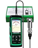
- PROFESSIONAL VIBRATION ANALYZER – VM-428 WITH EXTERNAL SENSOR - Designed for advanced vibration diagnostics on motors, turbines, pumps, compressors and rotating machinery where higher measurement ranges and additional diagnostic parameters are required.
- 5-PARAMETER MACHINE DIAGNOSTICS – A V D FREQUENCY TEMPERATURE - Measures Acceleration 0.1–300 m/s² (peak), Velocity 1–850 mm/s (RMS), Displacement 1–3300 µm (p-p), Frequency 30Hz–14kHz and Temperature, providing multiple diagnostic indicators for machine condition evaluation.
- DUAL FREQUENCY MEASUREMENT CIRCUIT – STRUCTURAL AND HIGH-FREQUENCY MODES - Low frequency mode supports general vibration analysis of machine structures, while high frequency mode allows observation of higher-frequency vibration signals often associated with mechanical wear or bearing conditions.
- REMOTE MAGNETIC SENSOR – STABLE AND REPEATABLE MEASUREMENTS - External piezoelectric shear-type probe with magnetic base allows secure placement on metal housings, supporting stable readings during inspection of motors, gearboxes and rotating equipment.
- ISO MACHINE CONDITION RATING INDICATION - Built-in vibration severity scale based on ISO vibration classification helps technicians visually interpret measured velocity levels during machine condition evaluation.
ISA material describes native interfaces and standardized information exchange, while Beckhoff positions data collection for monitoring, predictive maintenance, alarms and process optimization. Neither removes the need to define what a valid value means at this particular plant.
Choose the least disruptive viable architecture
Evaluate three patterns against the installed base, required latency, data completeness, control separation, cybersecurity, maintainability, vendor support and outage tolerance. The right answer can differ by process area.
| Approach | Suitable when | Trade-offs to assess |
|---|---|---|
| Read native sensor or controller protocols | The existing device exposes the required data and a compatible, supported driver is available. | Device-specific configuration, undocumented semantics, protocol security, scaling errors and long-term driver support. |
| Add a gateway or edge controller in parallel | Data is needed from mixed legacy and newer devices while the existing control layer remains in service. | New hardware and software to maintain; tag mapping, time synchronization, failure behavior and security must be engineered. |
| Consolidate or migrate PLC, DCS or SCADA | Equipment is obsolete, unsupported, unsafe to maintain, or the required integration cannot be achieved reliably by an overlay. | Larger engineering and commissioning scope, configuration conversion, operator retraining, testing and planned downtime. |
Native-protocol access
When an instrument, PLC or drive already exposes the needed value, a read-only connection can avoid rewiring and preserve the control application. Verify the exact model, firmware, enabled options, address map, maximum polling rate, diagnostic registers and support status. A protocol name alone does not establish compatibility: two devices using the same protocol may represent data differently or require different licenses.
Parallel edge layer
An edge controller or industrial gateway can poll selected legacy devices, accept data from newer IIoT sensors and publish normalized tags to a historian or analytics platform. This is useful when the control system has no practical northbound interface, when several protocols must be combined, or when a pilot should not disturb a running loop. The edge layer must have its own backup, patching, clock, alarm and failure policy; it is not “free” just because it leaves the PLC program unchanged.
Controls migration or consolidation
A migration becomes more defensible when spare parts and vendor support have ended, undocumented changes make troubleshooting unsafe, cybersecurity requirements cannot be met, or many isolated interfaces are already consuming more effort than a replacement. ABB describes consolidation of mixed-vendor DCS, SCADA and PLC environments into an integrated HMI, while Honeywell describes migration approaches that can retain existing wiring, cabinets and program design in some projects. These are vendor-described capabilities, not a substitute for a site survey and detailed conversion plan.
Match protocols to devices and purpose
Protocol choice follows the installed equipment and the function of the connection. A field protocol that is appropriate for configuration or a slow measurement is not automatically appropriate for plantwide event delivery or closed-loop control.
| Interface | Where it may fit | Checks before deployment |
|---|---|---|
| Modbus | Common legacy device and controller communications, especially for straightforward registers and status values. | Register map, function codes, byte order, scaling, polling limits, timeout behavior and whether the connection is isolated and read-only. |
| HART | Smart field instruments where process variables, diagnostics or configuration are available over the instrument loop. | Multiplexer or interface hardware, device revision, loop loading, update time, command permissions and hazardous-area requirements. |
| OPC UA | Standardized exchange from capable controllers, servers or edge systems to supervisory, historian and analytics applications. | Namespace design, certificates, authentication, endpoint policy, browsing versus fixed tag contracts, update rates and firewall rules. |
| MQTT | Publish/subscribe onward exchange from an edge layer to an operations or enterprise data service. | Broker ownership, topic and payload schema, client identity, certificate handling, retained messages, quality metadata and loss-of-connection behavior. |
ISA InTech search-result material identifies Modbus and HART among common existing-device protocols and discusses OPC UA as a widely supported standardized interface. Vendor material also lists OPC UA, MQTT and other industrial protocols. Confirm every capability against the actual installed firmware, licenses and plant network policy; do not infer a secure or real-time connection from a protocol label alone.
Rank #3

- 【5-in-1 Diagnosis】The vibration meter supports measurements of Acceleration 0.1–300 m/s² (peak), Velocity 1–850 mm/s (RMS), Displacement 1–3300 µm, Frequency 30 Hz–14 kHz, Temperature 14~140°F. The vibrometer gauge meets the common predictive maintenance and condition check needs in workshops and production sites.
- 【Wide Range of Applications】This digital vibration analyzer is suitable for motors, HVAC systems, pumps, fans, generators, compressors, turbines, bearings, etc. The tester features ISO vibration intensity classification. You can quickly get a preliminary assessment of machine/vehicle vibration. Appropriate for mechanical maintenance technicians, engineers, QC inspectors, or even beginners.
- 【Large Storage & Transmission】This vibration meter supports automatic/manual recording (stores up to 8 MB ≈397,000 data points). It can transfer CSV and BMP files via PC software (compatible with Windows systems) or be used as a small-capacity USB drive. Handy for long-term trend analysis and batch data archiving of equipment records.
- 【Clear Display & Stable Measurement】The easy-to-read backlit screen enables data collection and interpretation under various lighting conditions. It clearly shows line graphs and real-time statistics of maximum/minimum/average values. The separate probe comes with a strong magnetic sensor, which helps access hard-to-reach areas and minimizes the impact of your movements on the results.
- 【User-friendly Design】The vibration detector comes with a portable carrying case for outdoor use. It supports automatic high/low-speed circuit switching, adjustable sampling time, screen brightness, calibration, unit switching, automatic power-off, machine-grade selection, low battery indicator. The included manual provides a detailed explanation of each function. Setup takes only a few seconds.
Keep monitoring separate from control
Start with a read-only data path whenever the objective is monitoring, trending or analytics. The new system should not silently write to a controller merely because a driver supports write commands.
Define three authority levels
- Read-only collection: values, status and diagnostics are copied to a historian, dashboard or model. Loss of the path must not alter the process.
- Operator-facing alarm: a validated condition is presented with a clear source, priority, acknowledgement rule and fallback when data is stale.
- Control action: a command or setpoint change can affect equipment or process behavior. This requires explicit authority, permissives, interlocks, latency limits, failure states, manual override, management of change and testing with process, controls and safety engineers.
For any write-capable design, document which system is authoritative, how a conflicting command is resolved, what happens when communications fail and how an operator can regain control. Functional-safety requirements, safety integrity level, hazardous-area suitability and loop latency are site-specific; the available vendor descriptions do not determine them.
Engineer security and resilience with the data path
Draw the source-to-destination route and assign an owner to every boundary. Include controllers, edge devices, servers, brokers, firewalls, remote-support links and cloud or enterprise destinations if present.
- Place assets in appropriate control, supervisory and enterprise zones, with only required routes and ports allowed.
- Use individual identities, strong authentication and certificate or key management where the technology supports them; remove default accounts and unused services.
- Specify encryption in transit where supported, but do not treat encryption as proof that the overall architecture is secure.
- Assign patch, antivirus or allow-listing, vulnerability-review and backup responsibilities without connecting unsupported equipment to an uncontrolled update process.
- Log authentication, configuration, firmware, protocol and command events, and define who reviews them.
- Document the remote-access route, approval process, session recording and emergency disconnect.
- Define local behavior when the historian, broker, edge device or external network is unavailable. A control loop should continue safely using its designed local logic, not an improvised substitute.
Honeywell describes encryption, authentication and a controller firewall in a migration offering; Rockwell describes security features for mining control networks. Such statements describe available capabilities, not evidence that a particular plant design is secure. Validate the complete architecture with the site’s OT-cybersecurity and functional-safety specialists.
Use this implementation sequence
- Set scope and acceptance criteria. Name one process area, asset class or decision. Define the tags, update rates, alarm behavior, target systems, success measures and rollback condition.
- Survey the installed system. Walk down instruments, panels, cabinets, network rooms and OEM skids. Compare drawings, PLC projects, HMI screens and historian tags with what operators actually see.
- Confirm compatibility. Check model, firmware, communication card, license, driver, address map, electrical interface, hazardous-area constraints and available spares. Record unknowns instead of assuming them.
- Choose the connection pattern. Prefer a supported native read path when it provides complete, trustworthy data. Add an edge layer when mixed protocols or legacy isolation make that safer. Escalate to migration when supportability, safety or integration scope justifies it.
- Design the data contract. Freeze tag names, units, scaling, timestamps, quality states, context, retention and stale-data rules. Assign ownership for each tag and each interface.
- Design zones and failure modes. Approve firewall rules, identities, certificates, backups, patching, remote access, clock synchronization and local behavior during loss of communications.
- Build a test environment or offline configuration. Validate drivers, register maps, namespace or topic structure, scaling and quality handling before connecting to live equipment. Use representative values and simulated bad states where possible.
- Install during an agreed window. Follow permit, isolation and change-control procedures. Preserve the original configuration, back up controller and HMI projects, label new wiring and keep the old path available until acceptance.
- Commission in stages. Check one signal at a time, then groups, then the application. Test normal values, out-of-range values, sensor failure, stale data, time shifts, communications loss, restart behavior, alarm acknowledgement, network load and cybersecurity controls.
- Obtain operational acceptance. Have operators and maintainers confirm that values, units, trends, alarms and diagnostics are understandable and useful. Capture as-built drawings, tag/interface lists, credentials in the approved vault, backups, support contacts and a rollback procedure.
- Operate and review. Monitor data quality, interface health, clock drift, capacity, security events and maintenance workload. Expand only after the pilot’s failure modes and support responsibilities are understood.
Honeywell describes site surveys, pre- and post-migration reports and commissioning support. ABB emphasizes planning brownfield work around a controlled downtime schedule. Those practices are especially important where a short interruption can stop crushing, grinding, flotation or dewatering production.
Do these 3 things before closing this tab:
1Scan for outdated or missing drivers - takes under a minute2Repair Windows errors before they cause bigger problems3Fix the driver behind crashes, sound loss and screen glitchesWorked example: conveyor-bearing vibration monitoring
Conveyor bearings are a practical first use case because condition data can support maintenance without immediately changing conveyor control. Beckhoff uses conveyor-bearing vibration as an example of mining condition monitoring.
Specify the measurement
Choose the bearing locations, vibration quantity and frequency range required by the maintenance decision. Confirm mounting method, enclosure and environmental rating, temperature range, cable or wireless power needs, calibration, sampling and signal interface. An industrial vibration sensor is suitable only when its mounting, environment and output match the plant design; a marketplace description alone is not an engineering specification.
Rank #4
![[BLE Vibration Sensor] WTVB01-BT50 Smart Vibration Module Ar-duino, 3-axis Vibration(Amplitude+Frequency+Displacement+Speed) Detector, Wireless Acceleration Shock Motor Monitor](https://m.media-amazon.com/images/I/41va7oLvGmL._SL160_.jpg)
- 【Integrated Vibration Sensor】Real-time capture of 3-axis vibration and temperature data: Vibration displacement (0~30000um) + Speed (0~50mm/s) + Amplitude (0~180°) + Operating temperature (-20°C~60°C). Vibration and shock omnidirectional measurements can prevent breakdowns and repair costs.
- 【BLE 5.0 Low Power】 50m transmission distance, approximately 8 hours battery life. Bluetooth 5.0 is compatible with Android/iOS systems. The WITMOTION APP supports connecting sensors on smartphones (up to 4 on the same phone). It can also be connected to a computer via TYPE-C, making it easy for users to choose the best connection.
- 【Easy Install & Use】The wireless design allows the sensors to be installed on machine parts that are difficult to access. A small and portable sensor designed with strap holes at both ends that can be used and go anywhere.
- 【Analysis Vibration Sensor System】Condition monitoring and vibration analysis are seamlessly integrated with WITMOTION PC software, making it quick and easy to analyze and visualize data. Maintenance teams can set it up as needed.
- 【Attitude Measurement More Accurate & Reliable】Sensors integrated R&D fusion algorithm, low noise level, and increasing measurement accuracy ensuring stable data output. WITMOTION has been focusing on the sensor field for 10 years, providing professional attitude measurement solutions globally.
Connect without disturbing the conveyor loop
If the sensor or an existing monitoring module exposes a supported interface, collect its value through that interface. If the conveyor has a legacy controller and the new sensor uses a different protocol, a parallel edge device can normalize selected vibration, speed, load and bearing-identity tags. Keep conveyor start/stop logic in the existing control system unless a separate controls project proves a need to change it.
Make the alert actionable
Define a baseline period, data-quality state, trend interval, alarm thresholds, acknowledgement and maintenance response with the reliability team. A work order should identify the conveyor, bearing, timestamp, value, units, quality and operating context. Test sensor disconnection, a frozen value, edge-device failure and loss of the historian before calling the pilot successful.
Quick wins for a faster PC:
Fix the driver behind crashes, sound loss and screen glitchesFind Drivers →Repair Windows errors before they cause bigger problemsFix Now →Scan for outdated or missing drivers - takes under a minuteDriver Scan →The same pattern can be applied to grinding, flotation or plant optimization: start with a decision, collect only the variables needed, preserve context and prove the failure behavior before expanding.
Commissioning pitfalls and recovery actions
Values are readable but wrong
Typical causes are reversed byte order, incorrect integer scaling, engineering-unit conversion, a wrong register offset or a stale cached value. Compare the received value with a calibrated local indication across several operating points, verify raw bytes and document the conversion in the tag contract.
Tags appear valid but lose meaning
A number without source status, timestamp, mode, device identity or process context can mislead an analyst. Add quality flags and contextual tags, reject stale data in the receiving application and define ownership for each semantic change.
The new path overloads an old controller or network
Excessive polling, short timeouts and duplicate subscriptions can consume scan time or bandwidth. Start with the minimum tag set, respect documented polling limits, aggregate at the edge where appropriate, monitor controller and network load, and increase rates only when the control-system owner approves them.
What’s actually slowing this PC down?
Pick the symptom - the matching free tool is one click away.
An alarm chatters or arrives too late
Check sensor noise, deadband, timestamp source, buffering, clock synchronization and the route between source and HMI. Separate an advisory analytics notification from a process alarm until the alarm has a defined priority, response and validation.
Best Value
A migration loses operator confidence
Configuration conversion can alter tag names, graphics, alarm priorities or faceplate behavior even when the control narrative appears unchanged. Run parallel reviews with operators, preserve screenshots and approved alarm lists, provide training and retain a tested rollback point until acceptance.
The interface works in a test room but fails in production
Production may have different firewall rules, address conflicts, electromagnetic conditions, scan loads, time sources or maintenance procedures. Commission through the actual approved network path, test during representative operating states and record the as-built configuration rather than relying on a laboratory result.
When to bring in a specialist integrator
Use qualified controls, instrumentation, process, cybersecurity and functional-safety engineers when the project crosses an operational or safety boundary. An integrator is particularly valuable when several OEM skids must be coordinated, documentation is incomplete, a legacy controller has no supported interface, a migration must preserve a large program and HMI estate, or the outage window is too short for discovery during installation.
Ask for a site-survey report, interface and tag list, compatibility findings, network and security design, test procedures, outage method statement, rollback plan, training plan and as-built deliverables. Require clear ownership of licenses, backups, certificates, spare hardware, patching and post-commissioning support. “Can connect” is not enough; the deliverables must show how the connection behaves when data is wrong, delayed or unavailable.
How to decide whether to expand
After the pilot, review evidence rather than the number of tags collected. Continue when the selected data is accurate enough for the stated decision, operators understand the alarms or trends, failure behavior is safe, cybersecurity controls are operating, and someone is funded to maintain the interface. Re-scope when data quality is poor, ownership is unclear, the edge layer has become a second unsupported control system, or the business case depends on unmeasured production gains.
There is no universal sensor-to-PLC wiring diagram, protocol choice, functional-safety level or latency requirement for every mineral-processing plant. Controller age, enabled options, documentation, network policy, hazardous-area classification and process dynamics determine the design. Treat vendor capabilities as options to verify and make the final architecture a documented, site-specific engineering decision.
Quick Recap
Product prices and availability are accurate as of the date/time indicated and are subject to change. Any price and availability information displayed on Amazon at the time of purchase will apply.
Free tools Windows power users keep installed
One-click scans. No signup required.

