A 3D-printed PC accessory fits reliably when it is designed from measurements of your assembled computer, not from a generic case drawing. Define one job, measure the installed hardware and the space needed to install and service the part, model the critical dimensions so they can be changed, print a small interface test, then revise and validate the finished part in the case.
“PC” here means a personal computer. The same workflow applies to a cable guide, clip, bracket, spacer or dust-filter frame, but no single design can fit every case and component combination.
As an Amazon Associate I earn from qualifying purchases.
Start with the job, not the shape
Write down what the accessory must do and what it must never do before opening CAD software. A useful specification is short enough to check after installation:
- Function: for example, route one cable along a panel, support a bracket, create a spacer or hold a filter.
- Attachment: identify an existing screw hole, rail, edge, slot, magnet location or other feature you can use without drilling the case.
- Clear boundaries: state which surfaces, connectors, fans, heatsinks, circuit boards and cables the part must not touch.
- Service requirement: decide whether the part must come off for a side panel, drive, filter, GPU, cooler or cable to be removed.
- Failure containment: ensure a broken or detached part cannot fall into a fan or bridge exposed electrical contacts.
For a cable guide, the boundary might be “holds the cable against this panel, does not pinch the insulation, leaves the nearby fan opening clear and can be removed without disconnecting the cable.” For a spacer, it might be “positions this panel without moving it into the graphics card’s clearance envelope.” These statements prevent a visually attractive design from creating a new problem.
#1 Best Overall

- Spacious Design: Measuring 21.1" wide and 14.1" deep, our lap desk comfortably fits most laptops up to 15.6". Extra room for accessories ensures convenience.
- Enhanced Functionality: Packed with handy features, including a 5x9" precision tracking mouse pad and a built-in phone slot for seamless work or video calls. Plus, enjoy ergonomic support with the integrated cushioned wrist rest.
- Cool Comfort: Enjoy a stable surface with our lap desk's dual bolster cushion, designed for comfort and airflow, keeping your lap cool during extended use.
- Durable Surface: Work with confidence on our lap desk's solid surface, featuring a sleek black carbon color, ensuring optimal air circulation to prevent your laptop from overheating.
- On-the-Go Convenience: With an integrated handle and lightweight design (2.8 lbs), our lap desk is portable for travel or moving around the house, offering flexibility in any space.
Measure the computer you will actually install it in
Case model numbers and nominal component dimensions are useful for orientation, but they do not describe every installed combination. Motherboard position, radiator thickness, fan choice, cable routing, drive cages and manufacturing variation all change the available space. Measure the assembled system with the computer powered down, unplugged and cool enough to handle.
Use a consistent measurement reference
Choose datums: surfaces or holes from which other dimensions are taken. A case panel, the center of a screw hole, or a motherboard tray edge can serve as a datum. Record each measurement with its datum and direction instead of keeping isolated numbers in your head.
Digital calipers are useful for hole diameters, wall thicknesses, slot widths and the dimensions of a printed test piece. For larger gaps, a ruler or depth gauge may be easier. Take each critical measurement more than once and record the value you intend to model, the measured value and any uncertainty caused by access or flexing panels.
Do these 3 things before closing this tab:
1Fix the driver behind crashes, sound loss and screen glitches2Clear out junk files and repair common Windows errors3Scan for outdated or missing drivers - takes under a minuteCapture the complete installation envelope
- Attachment geometry: hole centers, hole diameter, screw-head clearance, edge thickness, slot length and the direction in which the accessory must slide or rotate into place.
- Nearby hardware: fan frames, blades, heatsinks, GPU backplates, memory latches, pumps, drive trays and structural ribs.
- Cable path: connector size, bend direction, bend space and the distance at which the cable must leave the guide.
- Access space: the room needed for a screwdriver, fingers, a plug, a removable filter and the motion of a panel or latch.
- Air openings: the full inlet and outlet area around the intended location, not just the visible hole directly under the part.
- Removal path: the route used to take the accessory out after the case is assembled.
Measure with cables and components installed when the accessory will be used that way. A cable may occupy more space in its final bend than its straight diameter suggests. A panel may appear to have room until a connector is inserted. If a dimension depends on a flexible cable, measure the actual bend you can make without stressing the connector.
Separate fit dimensions from clearance dimensions
Fit dimensions locate the part: a hole center, tab width or rail position. Clearance dimensions protect movement and service access: space around a plug, a fan blade or a removable panel. Keep them as separate parameters in your notes and CAD model. Tightening a fit dimension must not silently reduce a clearance dimension.
Build an adjustable CAD model
The first model should be easy to revise, because the printer and material will reveal the real fit. Name or group the dimensions that are likely to change:
Rank #2

- 5-in-1 Connectivity: Equipped with a 4K HDMI port, a 5 Gbps USB-C data port, two 5 Gbps USB-A ports, and a USB C 100W PD-IN port. Note: The USB C 100W PD-IN port supports only charging and does not support data transfer devices such as headphones or speakers.
- Powerful Pass-Through Charging: Supports up to 85W pass-through charging so you can power up your laptop while you use the hub. Note: Pass-through charging requires a charger (not included). Note: To achieve full power for iPad, we recommend using a 45W wall charger.
- Transfer Files in Seconds: Move files to and from your laptop at speeds of up to 5 Gbps via the USB-C and USB-A data ports. Note: The USB C 5Gbps Data port does not support video output.
- HD Display: Connect to the HDMI port to stream or mirror content to an external monitor in resolutions of up to 4K@30Hz. Note: The USB-C ports do not support video output.
- What You Get: Anker 332 USB-C Hub (5-in-1), welcome guide, our worry-free 18-month warranty, and friendly customer service.
- attachment-hole spacing and diameter;
- wall or tab thickness;
- cable opening width and height;
- clearance around the mating feature;
- overall length, height and offset;
- lead-in chamfers or radii;
- the position of ribs, clips and screw bosses.
Keep the functional interface simple. A flat plate with a wall, a hole and a modest fillet is easier to measure and revise than a decorative enclosure with many unsupported surfaces. Add a chamfer or lead-in where a tab must slide into a slot. Use a generous radius at the root of a clip or bracket rather than a sharp inside corner that concentrates stress.
Design around the print orientation
Decide how the part will sit on the print bed before finalizing thin features. A clip that is strong across its layers may be weak if the load tries to separate those layers. Rotate the part so the expected load is carried as much as practical within layers, and increase the thickness of thin tabs that must flex repeatedly.
Avoid long, thin unsupported spans when a rib, shorter span or different orientation can perform the same job. Manufacturer guidance for both material-jetting and fused-deposition processes warns that slender geometry can warp, and FDM guidance for PC-ISO notes that layer-related weak points must be considered. The exact support and orientation choice depends on your printer, material and geometry.
Design the attachment for real installation
If an existing screw is available, model a clearance hole and enough space for the head and tool. If the accessory slides over an edge, include a lead-in and a stop so it cannot migrate toward a fan or connector. If it clips on, make the clip replaceable or sacrificial rather than trapping an expensive component.
Do not make a snap fit the first interface you test. A removable screw, a loose locating tab or a temporary strap lets you verify position before committing to a tight spring feature. Once the measured fit is repeatable, you can refine the attachment without rebuilding the rest of the accessory.
What’s actually slowing this PC down?
Pick the symptom - the matching free tool is one click away.
Understand what tolerance numbers do—and do not—mean
There is no universal clearance for a 3D-printed PC part. Dimensional fit depends on part size, geometry, orientation, printer calibration, slicing settings and material, as Prusa Research explains in its modeling guidance. Treat every published number as a starting point tied to a particular process.
Rank #3
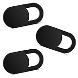
- Note: Not suitable for MacBooks released after 2023 or devices with a protruding front camera; Not applicable to full-screen or notch-style tempered glass screen protectors; Do not use on the rear camera of the phone.
- 💻 Why Do You Need a Webcam Cover Slide? — Safeguard your privacy by covering your webcam with our reliable webcam cover when not in use. Don't let anyone secretly watch you. Stay protected!
- ✅ Thin & Stylish — Enhance your laptop's functionality and aesthetics with our 0.027" ultra-thin webcam covers. Seamlessly close your laptop while adding a touch of sophistication.
- ✅ Fits Most Devices — Compatible with laptops, phones, tablets, desktops! Keep your privacy intact on Ap/ple, Mac/Book, iPh/one, iP/ad, H/P, L/novo, De/ll, Ac/er, As/us, Sa/msung devices.
- ✅ 365 Days Protection — Our upgraded 3.0 adhesive ensures a strong hold that won't damage your equipment. Experience reliable, long-term privacy protection day in and day out.
| Figure | Scope | How to use it |
|---|---|---|
| 0.3 mm initial gap | Prusa Research guidance for a movable part on an Original Prusa; the page does not establish this as a universal tolerance. | Use only as an initial experiment for that context, then print and adjust a coupon on your own machine. |
| 0.4 mm starting gap | HP Multi Jet Fusion guidance for connecting parts; moving assemblies have separate considerations. | Evidence that process changes the required gap, not a recipe for hobby FDM printing. |
| 0.15% standard accuracy, lower limit on ±0.2 mm | Materialise guidance for its FDM PC-ISO process. | Keep the stated process and material attached to the figure; do not apply it to every FDM printer or filament. |
The practical answer is to print a small test using the intended printer, material, orientation and settings. A test that fits on one machine may bind on another even when the CAD dimensions are identical.
Print a fit coupon before the full accessory
A fit coupon is a small, cheap representation of the interface. It should contain the hole, tab, slot, clip or cable opening that determines whether the part works. Do not print the entire bracket merely to discover that a screw hole is 0.2 mm off.
- Copy the measured interface into a test model. Include the surrounding wall or edge so the test has the same stiffness and orientation as the real feature.
- Make several controlled variants. Change only the clearance or thickness between variants. Keep labels on the model or in the file name so you know which dimension produced each result.
- Slice with the planned production settings. Use the same layer height, perimeters, infill approach, supports and orientation you expect for the final part.
- Measure the printed coupon. Check hole size, tab thickness, slot width and warping with calipers where possible. Note elephant-foot effects, support scars and any layer separation.
- Test it in the powered-off case. Insert it along the real installation path. Check both the intended fit and the removal path; a part that goes in but cannot be removed is not a successful fit.
- Change the CAD parameter, not the physical part. Record the observed error and revise the named dimension. Avoid filing away a critical interface unless you are deliberately creating a one-off adjustment and can keep the result safe.
- Repeat only the interface test. Once the coupon works, print the full accessory with the same process and orientation.
For a movable clip, test the complete flexing motion and leave enough room for the clip to release. For a cable guide, test with the actual cable and connector, not just a bare length of wire. For a screw-mounted bracket, test with the intended screw and tool access.
Crashes, No Sound, or Screen Glitches?
Random freezes, missing sound and display glitches usually trace back to one bad driver. Find and replace yours safely.Free scan · under a minutePC Slower Than It Used to Be?
A free scan shows the junk files, broken settings and background clutter dragging Windows down - then fixes them in one click.Free scan · Windows 10 & 11Choose a material for the printer and the location
Material selection is a joint decision about printer capability, part geometry and the environment inside the case. Check the printer and filament manufacturer’s requirements before selecting a material; a material that is mechanically attractive may be difficult or impossible to print reliably on your machine.
When polycarbonate is appropriate
Prusa Research describes polycarbonate (PC) as suitable for technical parts that need high mechanical and temperature resistance, while also noting that it is challenging to print. That makes PC a possible choice for a mechanically loaded or warmer location when your printer can process it consistently. It does not make PC automatically safe beside every component, nor does it remove the need for an enclosure, suitable build surface, drying practice or other requirements specified for your printer and filament.
Match the material to exposure
- For a part near heat, identify the actual nearby surfaces and operating conditions rather than assuming a generic “inside a PC” temperature.
- For a flexing clip, prioritize repeatable layer bonding and a geometry that does not overstress the layers.
- For a cosmetic dust frame, focus on dimensional stability, the filter’s retention method and whether the material can be printed cleanly in the chosen orientation.
- For any material, confirm that the printer can produce the required dimensions and that the finished part does not shed fragments into fans or connectors.
No material should be described as universally safe near all PC components without testing the actual location and operating conditions.
Rank #4

- Anti-Slip Surface - Transform your laptop into a mobile workstation with the AboveTEK portable laptop lap desk. The anti-slip surface provides a strong grip for laptops up to 15.6 inches(Diagonal), while the double rubber strip on the bottom ensures a stable display or typing experience on your lap, couch, or bed.
- Retractable Mouse Pad - Retractable laptop mouse pad extends on both directions for the left/right handed with elevation along the edges for stopping mouse from falling off. The size of laptop tray is 14" X 9.7" and the size of mouse pad is 7.4" X 6.1".
- Effective Heat Shield - The effective heat shield made of sturdy and thick material protects your laptop from overheating. Prioritizes your comfort and safety, an ideal lap pad or board for working anywhere.
- EASY to Carry and Store - With an ergonomic and simplistic design, the lap desk is portable to store in a backpack. Only 15" in size, 2.2 lb of weight and with slim 0.6 inch thickness, it is ready to be easily carried around.
- Widely Applicable - The smooth platform accommodates laptops and tablets up to 15.6 inches(Diagonal), making it a versatile accessory and one of the best gifts for mom, dad, students and professionals. Perfect for use as a laptop bed tray or tablet holder anywhere at home, library, or park.
Make the printed part durable and serviceable
Protect thin clips and tabs
Put the load into the broad face of a clip where possible, add a root radius and avoid a long unsupported lever. If a tab must flex, make the flexing length and direction intentional and test it repeatedly before installation. A replacement clip is easier to service when it is a separate part rather than an integral feature that requires removing a motherboard.
Free tools Windows power users keep installed
One-click scans. No signup required.
Control warping and unsupported geometry
Long, thin sections are vulnerable to warping. Shorten a span, add a rib, change the print orientation or split the part into pieces that can be joined at a controlled interface. Supports can improve a surface but also leave marks and alter a mating dimension, so include those effects in the fit coupon.
Plan fasteners and inserts only when needed
Use the hardware required by the chosen design, not a generic kit. A screw-through hole, a captive nut or a heat-set insert each needs its own measured clearance and installation access. If you cannot reach the fastener after the accessory is installed, redesign the service sequence before printing.
Independent reader supportYour contribution helps us test, update, and keep practical guides available for everyone.Keep airflow, moving parts and service access clear
Install the accessory only after checking the whole surrounding system. Leave fan inlets and outlets, moving blades, connectors, latches and removable components unobstructed. There is no generally valid “safe distance” for an aftermarket printed part around a fan or vent; the available evidence does not establish one universal value or a thermal test that applies to every case.
After installation, inspect the part with the case open and the fans stopped. Confirm that no edge can contact a blade, cable insulation is not pinched, and the part cannot slide into an opening. Close the panels and repeat the inspection through the complete service path: remove the filter, unplug the cable, open the panel or remove the component that the accessory is intended to coexist with.
The Tool Desk
Outbyte PC Repair FREEClear out junk files and repair common Windows errorsFree Scan →Outbyte Driver Updater FREEScan for outdated or missing drivers - takes under a minuteDriver Scan →Validate operation instead of assuming a cooling benefit
If the accessory is near airflow or a heat-producing component, monitor the system using its own sensor software or the component manufacturer’s guidance. Compare operation with and without the accessory under the same workload if airflow is important. Treat the result as a validation check, not proof that the printed part improves cooling; an untested accessory should never be advertised as a thermal upgrade.
Best Value

- Spacious Design: Measuring 21.1" wide and 12" deep, our lap desk comfortably fits most laptops up to 15.6". Extra room for accessories ensures convenience.
- Enhanced Functionality: Packed with handy features, including a 5x9" precision tracking mouse pad and a built-in phone slot for seamless work or video calls. Plus, enjoy laptop support with the integrated device ledge.
- Cool Comfort: Enjoy a stable surface with our lap desk's dual bolster cushion, designed for comfort and airflow, keeping your lap cool during extended use.
- Durable Surface: Work with confidence on our lap desk's solid surface, featuring a blush pink color, ensuring optimal air circulation to prevent your laptop from overheating.
- On-the-Go Convenience: With an integrated handle and lightweight design (2.14 lbs), our lap desk is portable for travel or moving around the house, offering flexibility in any space.
Four useful accessory patterns
| Accessory | Measure first | Design priorities | Typical validation |
|---|---|---|---|
| Cable guide | Attachment edge or hole, cable diameter, connector and bend route | Rounded contact surfaces, release path, no pinching, no blocked vent | Install with the real cable connected and verify that the cable can be removed without pulling the connector. |
| Clip | Edge thickness, insertion direction and required flex travel | Layer direction, root radius, replaceable or sacrificial feature | Cycle the clip through installation and removal while checking for cracks or whitening. |
| Bracket | Hole centers, screw-head clearance, supported load and tool access | Load path, ribs, broad mounting face and service access | Fit with the intended fasteners, then apply the expected load while the computer is powered off. |
| Spacer | Both mating surfaces, final offset and neighboring clearance envelopes | Compression resistance, anti-rotation feature and correct stack height | Install the adjacent component and confirm that connectors, panels and latches still operate. |
| Dust-filter frame | Opening perimeter, retention points and filter thickness | Even sealing, easy removal and unobstructed airflow area | Remove and reinstall the filter, then inspect for loose fragments and panel interference. |
These are patterns, not universal models. The measured interface and the service path determine the final dimensions.
A repeatable end-to-end workflow
- Define one job and its prohibitions. Write the function, attachment, surfaces it must not touch and the maintenance action it must permit.
- Power down and measure the assembled build. Establish datums, record mounting points, capture cable bends and measure installation and removal space.
- Create named CAD parameters. Keep attachment, wall thickness, opening, offset and clearance dimensions editable.
- Choose an orientation and material. Base the decision on expected load, heat, printer capability, support needs and layer direction.
- Model a simple first version. Add lead-ins, radii and ribs where they solve a real installation or strength problem.
- Print a coupon. Use the intended printer, material, orientation and settings; test the real interface rather than the whole part.
- Measure, fit and revise. Record the printed dimensions and change the CAD parameter that caused the mismatch.
- Print the production part. Preserve the coupon’s proven process and orientation unless the geometry has changed.
- Install with the computer off. Check attachment security, cable strain, fan clearance, panel movement and service access.
- Validate during operation. Watch for vibration, rubbing, heat-related deformation and airflow changes; remove the part immediately if it interferes with a moving or electrical component.
Troubleshoot the common failures
The part is too tight
Check for elephant foot, support residue, hole shrinkage, a warped wall or a measurement taken at the wrong datum. Measure the printed feature, revise the relevant parameter and reprint the coupon. Do not enlarge every opening indiscriminately: a loose attachment can let the part migrate into a fan or connector.
The part is too loose
Verify that the case edge or hole was measured with the same component installed. Add a locating shoulder, a screw, a stop or a controlled shim rather than relying on friction alone. If the fit changes with temperature or load, test the installed part under those conditions before trusting it.
The clip breaks along a layer line
Change the orientation so the flexing load is less dependent on layer adhesion, thicken or shorten the flexure, add a root radius, or choose a material and process that your printer can reproduce reliably. Reprint and cycle-test the coupon before installing the full part.
A long section warps
Reduce the unsupported length, add a rib, split the model, change orientation or revise the bed-adhesion and support strategy. Measure the warped interface; compensating in CAD is useful only after you understand which feature moved.
The accessory blocks a panel or cable
Recheck the removal path with the case assembled. A successful static fit is not enough if a side panel cannot close or a connector cannot be unplugged. Move the accessory, add a lead-in or redesign the attachment so the required service motion remains possible.
The accessory affects cooling or makes noise
Power down and inspect for contact with a fan, cable vibration, a blocked opening or a loose resonant panel. Compare monitored operation with and without the part under the same workload. If the cause is not clear, remove the accessory rather than guessing at a safe clearance.
Document the finished design
Keep the final CAD file with its named dimensions, the measured datums, printer and material, orientation, slicer settings, coupon result and installation notes. Photograph the installed part and record which components were present. If you later change a fan, radiator, graphics card, cable route or case panel, treat the accessory as a new fit check rather than assuming the old dimensions still apply.
The best custom PC accessory is not the most elaborate model. It is the smallest reliable part that performs a defined job, survives its actual loads and conditions, leaves the system’s moving, electrical and service functions intact, and can be revised when the build changes.
Quick Recap
Product prices and availability are accurate as of the date/time indicated and are subject to change. Any price and availability information displayed on Amazon at the time of purchase will apply.

