You can daisy-chain compatible PC fans to reduce cable clutter and let several fans share one control connection, but there is no universal safe fan count. The limit is set by the exact fan model, what the chain carries, and the documented current or signal limit of the motherboard header or controller. Add the rated current of every fan powered by one header, compare that total with the header’s specification, and use a compatible powered hub when the total or connector count is too high.
“Daisy chaining” can mean pass-through PWM power and control, RGB lighting connections, or a separate low-voltage control link. Those systems use different connectors and limits. A lighting limit never substitutes for a motor-current limit, and wiring fans in a chain does not itself improve temperatures, noise, or energy use.
As an Amazon Associate I earn from qualifying purchases.
What daisy chaining a fan actually means
A daisy chain connects one fan to the next so a single motherboard header or controller reaches several devices. The first fan plugs into the board or controller; additional fans use a pass-through connector built into the preceding fan or its cable. Depending on the product, the chain may carry motor power, PWM speed control, a tachometer signal, RGB data and power, or only a control signal while power comes from another source.
Windows Errors? Fix Them Before They Spread
Repair common Windows errors and clear accumulated junk for a smoother, more stable PC - no reinstall needed.Free scan · no reinstallCrashes, No Sound, or Screen Glitches?
Random freezes, missing sound and display glitches usually trace back to one bad driver. Find and replace yours safely.Free scan · under a minuteThat distinction matters because two products can both advertise “daisy chaining” while having completely different electrical limits. A fan chain designed for PWM motor power cannot automatically carry an RGB load, and an RGB controller’s LED limit says nothing about how much motor current a motherboard header can supply.
#1 Best Overall
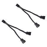
- Length 240mm, pack of two computer fan splitter cables
- One-to-two PWM fan splitter
- Beautiful all black sleeved cable
- Supports 2 PWM fans from a single motherboard PWM header
- Compatible with 4pin PMW fan connector and 3pin fan connector
What chaining can and cannot change
- It can simplify wiring. Fewer cables need to run back to the motherboard, which helps cable management and can make a clean installation easier.
- It can synchronize control. Fans connected to one PWM header normally follow the same duty-cycle command, subject to the fan and controller design.
- It does not create extra electrical capacity. Every fan still draws current from the header or power source specified by the design.
- It does not guarantee identical speed reporting. Many chains expose only one tachometer signal. ARCTIC says of its P12 PWM PST chain, “The speed monitoring will be done on the first fan in the daisy-chain” (ARCTIC P12 PWM PST support page, accessed October 13, 2026).
- It does not improve cooling by itself. Temperatures depend on fan selection, placement, direction, case restrictions and speed settings, not on whether the cables are linked in series.
How many fans can you safely chain?
There is no motherboard-wide number that applies to every fan. Calculate the load for the exact chain:
Total fan current = fan 1 rated current + fan 2 rated current + … + fan n rated current
Compare that sum with the current rating printed in the motherboard manual for the specific fan header. If the manual also gives startup or peak-current guidance, use that value rather than relying only on the steady-state rating. The relevant comparison is the load on the particular header or controller, not a generic number found on another board.
Worked examples using manufacturer figures
CORSAIR’s RS Series guide gives model-specific input ratings of 12 V DC, 0.4 A for the RS120 and 12 V DC, 0.45 A for the RS140. The same guide says that most motherboard fan headers can typically provide up to 1 A, “which would be about 3 fans” (CORSAIR RS Series guide, accessed October 13, 2026). Those are examples, not a specification for your board.
- Three RS120 fans would total 1.2 A (3 × 0.4 A), exceeding a 1.0 A example header rating.
- Two RS140 fans would total 0.9 A (2 × 0.45 A), which is below that example rating, provided the motherboard manual permits the load and no higher startup requirement applies.
- Mixing models requires adding each model’s own rating; do not substitute the lower-current fan’s figure for the entire chain.
Noctua frames the same decision around the selected fans and the capacity of the chosen header in its FAQ, “Can I connect multiple fans to one fan header?” (Noctua FAQ, accessed October 13, 2026). The FAQ is useful for the method, but it cannot replace the manual for your particular motherboard.
Rank #2

- Triple Fan Connection Solution: The 4 pin fan splitter cable connects up to 3 computer case fans to a single motherboard fan header. This PWM splitter cable lets you add an additional fan to improve airflow inside your PC. A fan speed label on the 4 pin master connector of the fan header splitter is wired to receive the PWM control signal and distribute it to all slave fans for synchronized cooling.
- Unified PWM Control: The 3 way fan splitter (also known as a motherboard fan splitter, CPU fan splitter, or PC fan splitter 4 pin) connects to a 4-pin motherboard header and splits the signal across 3 PWM fans. Control fan speed uniformly through motherboard software for efficient, balanced cooling performance.
- Synchronized Speed Management: The 4pin fan splitter features one 4-pin connector that sends the RPM signal back to the motherboard to synchronize fan speed across the other two fans. The 3 pin fan splitter omits the RPM signal pin, allowing all connected fans to run in tandem when supported by your system—perfect for setups where you need to daisy chain PC fans for optimized airflow.
- Spare Cable Convenience Pack: This cost-effective 2-pack of computer fan splitter 4 pin cables includes a spare for future upgrades or extra fans. Each sleeved and wrapped black 12-inch case fan splitter cable provides a clean, professional look inside an open PC case and helps organize your cable management.
- Wide Compatibility for Enhanced Cooling: Compatible with both 3-pin and 4-pin fans, this PWM fan splitter cable works with popular models such as the Cooler Master Hyper 212 EVO 120mm, Cooler Master MegaFlow 200mm, and other large 230mm case fans. Easily expand your system’s cooling capacity with this reliable PWM fan splitter cable.
Why a manufacturer’s chain count is not universal
Some fan families publish a maximum number per cable or connector that includes the product’s wiring and controller design. For example, ARCTIC recommends limiting its P12 PWM PST chain to five fans because current may be limited to 1.0 A per header (ARCTIC P12 PWM PST support page). Thermaltake lists up to eight CT120 EX fans per cable, while its SWAFAN EX product information describes up to three fans per cable; ARGB versions can have separate restrictions (Thermaltake CT120 EX product page). These limits belong to those product lines and their specified cables. They are not permission to place the same number of another brand’s fans on any header.
Identify the chain type before connecting anything
PWM fan power and control
A conventional 4-pin PWM fan connector carries a 12-volt supply, ground, a tachometer signal and a PWM control signal. A pass-through design can let several motors share the header while the board sends one control command. CORSAIR states, “A 4-pin header is necessary for PWM control” in its RS Series guide (CORSAIR RS Series guide). A 4-pin fan may physically fit a 3-pin header, but that guide says it will not benefit from PWM control in that setup.
Quick wins for a faster PC:
Repair Windows errors before they cause bigger problemsFix Now →Scan for outdated or missing drivers - takes under a minuteDriver Scan →Clear out junk files and repair common Windows errorsFree Scan →Check whether the fan’s pass-through connector actually carries all four functions. Some products expose only power and control, while the tachometer is intentionally reported by one fan. Do not assume that every fan in a chain will appear as a separate RPM reading in firmware.
3-pin DC fan connections
Three-pin fans use voltage control rather than the dedicated PWM control pin. A motherboard may support DC mode on a 4-pin header, but the setting and behavior are board-specific. Confirm in the motherboard manual that the header can switch between PWM and DC modes, and make sure the fan’s minimum operating voltage is compatible with the control curve. If the board remains in PWM mode for a 3-pin chain, the fans may run at full speed or fail to respond as expected.
RGB lighting chains
RGB connectors are a separate circuit from the fan motor. Verify the voltage, pin arrangement, controller generation and total LED count before linking them. NZXT’s RGB connection guide specifies a limit of 40 LEDs per channel and says its F-Series RGB fans cannot be daisy-chained (NZXT RGB Connection Guide, updated August 29, 2024; accessed October 13, 2026). That is a lighting compatibility limit, not a motor-current rating.
Rank #3

- Dual Fan Connection: This PC fan splitter Y cable connects 2 computer case fans to a single motherboard fan header. This 1 to 2 case fan splitter is ideal for adding an extra fan to boost airflow inside your computer case.
- 4-Pin Fan Header Support: Mobo 4 pin fan splitter connects to the 4-pin header on your motherboard and splits the PWM signal to 2 PWM fans. Both fans can spin at the same speed using motherboard software with PWM control support.
- Sync for Consistent Speeds: Master/slave PWM splitter includes a 4 pin fan connector that transmits the RPM signal to the motherboard, ensuring synchronized fan speeds for both fans. The computer fan splitter omits the RPM signal pin on the second fan for tandem operation.
- Tidy Setup with PWM Y Cable: Double CPU fan splitter supports up to 4 fans using this cost-effective 2-pack of fan header splitter cables. The black-sleeved and wrapped 4-inch PWM Y splitter cable ensures a clean and organized build—perfect for open computer cases.
- Works with 3-Pin & 4-Pin Case Fans: 3-pin & 4-pin fan compatible with popular cooling fans such as Corsair Air Series AF120 80mm / AF140 High Airflow, Cooler Master Blade Master 80 / Master 92, Cooler Master Hyper 212 EVO 120mm, JetFlo 120mm, SickleFlow 120mm, MegaFlow 200mm, Noctua NF-F12, and Thermaltake WATER 3.0 Dual 240.
Never force a 5-volt, three-pin addressable-RGB plug into a 12-volt, four-pin RGB header, or connect a proprietary lighting plug to a standard header without the specified adapter. A connector that fits mechanically can still use the wrong voltage or data protocol. Count the LEDs in every fan and strip on the channel, then compare the total with the controller’s documented limit.
The Tool Desk
Outbyte PC Repair FREERepair Windows errors before they cause bigger problemsFix Now →Outbyte Driver Updater FREEScan for outdated or missing drivers - takes under a minuteDriver Scan →Proprietary control and industrial links
Some ecosystems use a dedicated controller, hub or data cable rather than a motherboard fan header. Hunter Industrial’s DDI installation manual, for example, specifies shielded Cat5e–6 cable and a maximum 300-foot cable distance for its industrial fan-drive communication chain (Hunter Industrial DDI Installation Manual). That is an industrial control system, not guidance for powering PC fans. Use the instructions for the exact system instead of applying PC fan-header calculations to it.
Manufacturer examples at a glance
The following figures show why the model and connector arrangement must be written down before you plan a chain.
| Product or system | Published figure or rule | What the figure applies to |
|---|---|---|
| CORSAIR RS120 | 12 V DC, 0.4 A input | Motor input for the RS120 model; compare the summed current with your header rating. |
| CORSAIR RS140 | 12 V DC, 0.45 A input | Motor input for the RS140 model; not a universal fan value. |
| CORSAIR RS Series guidance | Most motherboard headers can typically provide up to 1 A; about three fans as a rough example | Manufacturer guidance, not the specification for an unidentified motherboard. |
| ARCTIC P12 PWM PST | Recommend no more than five fans per header when current may be limited to 1.0 A | That fan and its PST chain; speed monitoring is on the first fan. |
| Thermaltake CT120 EX | Up to eight fans per cable | CT120 EX cable arrangement; do not transfer the count to another model. |
| Thermaltake SWAFAN EX | Up to three fans per cable | SWAFAN EX product-line guidance; ARGB variants may have separate limits. |
| NZXT RGB controllers | 40 LEDs per channel | Lighting-channel capacity, not fan-motor current. |
| NZXT F-Series RGB | Cannot be daisy-chained | Model-specific RGB restriction. |
Safe installation procedure
- Shut down and isolate the computer. Turn the operating system off, switch off the power supply and disconnect the mains cable before moving fan plugs. CORSAIR’s installation instruction is explicit: “Turn the computer off prior to the installation of the RS fans” (CORSAIR RS Series guide).
- Record every fan model. Write down each fan’s rated input current, connector type, voltage and any published maximum chain count. Include fans already connected to the same header; the new chain is not the only load that matters.
- Find the exact header limit. Open the motherboard manual and locate the electrical rating for the specific header you intend to use. Some boards provide different limits for CPU, pump and chassis headers. If the manual does not state a limit, contact the board manufacturer rather than assuming a 1 A value.
- Add the motor currents. Sum the nameplate or manual rating for every fan powered by that header. Keep startup or peak-current information in the calculation when the manufacturer supplies it. A steady-state sum that looks acceptable can still be unsafe if the design has a higher startup demand than the header permits.
- Confirm the pass-through design. Read the fan manual to verify that the chain connector is intended for the same fan family and that the specified number of links is allowed. A splitter, extension and pass-through connector are not interchangeable just because they use the same 4-pin shape.
- Separate motor and lighting plugs. Route the PWM or DC fan connector to a fan header and the RGB connector to the compatible lighting controller or header. Check voltage, pin count, keying and LED totals independently.
- Orient each plug correctly. Align the keyed side or guide rail before applying pressure. Do not bend pins or force a connector that does not slide on easily. Connect the first fan to the board or controller, then connect each subsequent fan to the preceding fan’s marked output.
- Connect the final link as directed. Some products require a terminator, a specific final plug or a separate controller connection. Follow the model’s diagram rather than leaving an unused proprietary connector attached to a random header.
- Use a powered hub when necessary. If the summed current exceeds the documented header capacity, the chain-count limit is lower than your requirement, or the board lacks enough compatible headers, select a hub that explicitly supports your fans. Verify the hub’s power source, maximum load, connector type and whether it mirrors one PWM signal or reports a tachometer before installing it.
- Test before closing the case. Reconnect power, start the system and check that every motor spins, the BIOS or operating system reads the expected control mode, and the lighting controller recognizes only the supported devices. Shut down immediately if a connector, cable or header becomes hot, smells of overheated plastic, or causes repeated power cycling.
Choosing between one header, several headers and a powered hub
| Approach | Use it when | Advantages | Risks or limitations |
|---|---|---|---|
| One supported daisy chain | The fan manual supports pass-through, the summed current is below the exact header limit, and one control curve is acceptable. | Least cable clutter; simple synchronized speed control. | One header carries the entire load; often only one tachometer is visible; a failed link can interrupt later fans. |
| Separate motherboard headers | The board has enough compatible headers and you want independent curves or easier fault isolation. | Distributes current and allows separate control zones. | More cables; each header still has its own current limit and must be checked. |
| Compatible powered fan hub | The chain would exceed a header’s rating, exceed the fan’s supported link count, or require more connectors than the board provides. | Moves motor power to the hub’s specified supply while preserving the intended control arrangement. | Hub limits and behavior vary; some mirror one PWM signal and expose limited tachometer information. Compatibility must be verified from the hub and fan manuals. |
| RGB controller or lighting hub | You need to connect multiple lighting devices and the controller supports their voltage, protocol and LED total. | Handles lighting data separately from motor power. | RGB capacity does not increase fan-header capacity; proprietary ecosystems may prohibit chaining. |
Cooling efficiency: what chaining changes and what it does not
Daisy chaining is a wiring and control choice, not an airflow technology. The available manufacturer material describes connection limits, current ratings and, for individual models, airflow or noise specifications. It does not establish a controlled comparison showing that the same fans cool better, run quieter or use less energy merely because they are chained.
To improve cooling, make the airflow decisions separately:
Recommended Free Tools
Rank #4

- Triple Your Cooling: Connect up to three 4-pin or 3-pin PWM case fans to a single motherboard fan header. Easily add extra fans to dramatically improve PC airflow and cooling performance for your CPU, GPU, or entire system.
- Unified PWM Control: This 3-way splitter features one master connector (with RPM sensing) and two follower connectors. It distributes a single PWM speed control signal from your motherboard BIOS or software for synchronized, uniform fan speed management across all connected fans.
- Ideal Length & 2-Pack Value: Each sleeved black cable is 10.6 inches (27 cm) long, providing ample reach for clean, organized cable management inside your PC case. The cost-effective 2-pack includes a spare for future upgrades or additional cooling setups.
- Wide Compatibility: Works seamlessly with both 4-pin PWM and 3-pin DC fans. Compatible with popular fan models from Cooler Master including large 200mm or 230mm case fans.
- Safe & Reliable Design: Built with quality materials to ensure stable power delivery and signal integrity. The splitter safely draws power directly from the PSU via the motherboard header, preventing overloading while enabling efficient, balanced cooling for your gaming rig or workstation.
- Choose a layout. Decide which fans are intake and which are exhaust, accounting for the case’s vents, filters and radiator locations.
- Set direction deliberately. Use the arrows molded into the fan frame or observe the blade curvature; do not assume the side with the support struts is the intake.
- Match the fan to the restriction. Radiators and dense filters need a fan designed for static pressure, while open mesh panels place more emphasis on airflow. Use the manufacturer’s published specifications for the exact model and test conditions.
- Build a control curve. A shared chain is convenient when all fans can follow the same temperature source. Separate headers or a hub with multiple channels are preferable when, for example, radiator fans and case exhaust need different responses.
- Check acoustics after installation. Fan noise depends on speed, turbulence, bearings, case panels and obstructions. Lowering the control signal may reduce noise, but only if the connected fan and header support the selected control mode.
Keeping cables tidy can make installation and maintenance easier, but it should not be presented as a cooling-performance gain.
Independent reader supportYour contribution helps us test, update, and keep practical guides available for everyone.Troubleshooting a daisy-chained setup
None of the fans spin
- Power the system off and verify that the first connector is on a fan header, not an RGB header.
- Check the header’s BIOS setting. A 3-pin chain may require DC mode; a 4-pin PWM chain requires a PWM-capable header and correctly seated control pin.
- Disconnect the chain and test one fan directly on the header. If one fan works alone but the chain does not, inspect each pass-through link and recalculate the total current.
- If the total is above the header rating, stop using that header and move the load to a compatible powered hub.
Fans run at full speed or ignore the curve
- Confirm that the motherboard header is configured for the connector type. A 4-pin fan on a 3-pin header may run without PWM control, as described in the CORSAIR RS Series guide.
- Inspect the pass-through plug for a missing or bent PWM contact.
- Check whether the fan family requires its own controller rather than direct motherboard control.
Only one RPM reading appears, or the reading is unstable
That can be normal for a chain designed to report the tachometer from only one fan. ARCTIC documents first-fan speed monitoring for its P12 PWM PST design. If the reading is zero, verify that the first fan is the one connected to the board’s input and that its tachometer contact is seated. Do not split or splice tachometer wires unless the manufacturer explicitly supports it.
One fan in the middle or at the end is dark
- Power down and reseat the pass-through connector at the last working fan.
- Check the product’s maximum link count; a chain can stop at its supported limit even when earlier fans operate normally.
- For RGB, verify voltage, pin arrangement, controller generation and LED count. A motor connection can be correct while the separate lighting connection is incompatible.
RGB flickers, resets or does not respond
Disconnect the lighting chain and compare its total LEDs with the controller channel limit. NZXT documents 40 LEDs per channel for its RGB controllers and prohibits daisy-chaining for F-Series RGB fans; those rules cannot be generalized to other products. Never connect a 5-volt addressable-RGB device to a 12-volt RGB output.
The computer shuts down or the header becomes hot
Turn the system off, unplug the chain and test a single fan. A protection shutdown or heat at the header is a warning that the load, wiring or connector is unsuitable. Do not continue testing by repeatedly powering an overloaded header. Recalculate the load from the fan labels, check for a shorted or damaged cable, and use a correctly rated powered hub or additional headers only after confirming compatibility.
A practical decision checklist
Before you connect the first plug, answer each question:
Best Value

- Efficient and Convenient: The 3 Way PC Fan Splitter is designed to efficiently distribute power to multiple fans, allowing for optimal cooling performance in your computer. With 2 Pcs of 4 Pin PWM Fan Splitters, this splitter provides a convenient solution for connecting and controlling multiple fans at once
- Versatile Compatibility: This Fan Header Splitter is compatible with both 4-pin and 3-pin cooling fans, making it suitable for various types of computer cases. Whether you have a high-performance gaming rig or a compact workstation, this splitter will ensure efficient airflow and temperature regulation
- Simplified Cable Management: Say goodbye to messy cables! The PC Fan Splitter 1 to 3 Converter simplifies cable management by consolidating multiple fan connections into a single cable. This not only improves the overall aesthetics of your computer but also minimizes the risk of cable tangling and obstruction
- Durable Construction: Constructed with high-quality materials, this Case Fan Splitter is built to withstand the demands of continuous usage. The 11-inch length provides ample reach and flexibility, allowing you to easily connect fans in different locations within your computer case
- Made of PVC Braided Rope and Stylish Design: Made of PVC braided rope black finish, this fan splitter seamlessly blends in with any computer setup. Its compact design ensures compatibility with various PC cases, while the durable connectors ensure a secure and reliable connection
- What exact fan models are included, and what current does each one specify?
- Is the proposed chain carrying PWM/DC motor power, RGB lighting, a proprietary signal, or more than one of these through separate connectors?
- Does the fan manufacturer explicitly support pass-through chaining, and what maximum count does it publish?
- What is the documented current limit of the exact motherboard header or controller?
- Does the sum of all connected fan currents stay below that limit, including any stated startup guidance?
- Will one tachometer reading and one shared speed curve meet your control needs?
- Are the lighting voltage, connector, protocol and LED total within the controller’s limits?
- If any answer is unknown, can you obtain the relevant manual or choose a compatible powered hub instead of guessing?
If you cannot verify the header rating or connector arrangement, do not rely on a chain-count claim from a different product. Use the motherboard, fan, controller and hub manuals as the authority for the final installation.
Frequently misunderstood points
Does a splitter count as daisy chaining?
Functionally, both arrangements let several fans share a control source, but their electrical paths differ. A passive splitter puts multiple loads directly on one header; a fan’s pass-through connector may include model-specific current handling, signal filtering or a designated tachometer path. Apply the limit for the actual accessory and fan design rather than treating every multi-fan cable as equivalent.
Can I chain fans from different brands?
Only when the connector, voltage, signal behavior and manufacturer documentation make the combination explicitly compatible. Standard 4-pin PWM motor plugs may look alike, but pass-through and RGB implementations can be proprietary. Mixed models also require adding each fan’s current, not multiplying one model’s rating.
Do these 3 things before closing this tab:
1Repair Windows errors before they cause bigger problems2Scan for outdated or missing drivers - takes under a minute3Clear out junk files and repair common Windows errorsWill chaining make all fans run at the same speed?
They generally receive the same control command when they share one PWM channel, but different motor designs can produce different RPM at the same duty cycle. A chain may also expose only one tachometer reading. If individual speed curves or per-fan monitoring are important, use separate headers or a controller that documents those functions.
Is a manufacturer’s “eight fans per cable” statement proof that my motherboard can power eight fans?
No. That statement applies to the named product, cable and intended controller arrangement. You must still compare the electrical load with the motherboard header or hub limit, and check whether the lighting side has a separate maximum.
Final guidance
Daisy-chain only a fan model and connector arrangement that explicitly supports it. Add the rated motor current for every fan on the powered header, compare the total with the exact header specification, and treat PWM control, tachometer reporting and RGB lighting as separate compatibility questions. When the load, chain count or connector support is uncertain, stop and use the manuals or a compatible powered hub rather than guessing. The result will be safer and easier to troubleshoot; the actual cooling improvement will come from the fans, airflow layout and control settings, not from the chain itself.
Quick Recap
Product prices and availability are accurate as of the date/time indicated and are subject to change. Any price and availability information displayed on Amazon at the time of purchase will apply.
Free tools Windows power users keep installed
One-click scans. No signup required.

