Do these 3 things before closing this tab:
1Repair Windows errors before they cause bigger problems2Scan for outdated or missing drivers - takes under a minute3Clear out junk files and repair common Windows errorsThere is no universal MGX power cable or networking bill of materials. MGX is a platform family implemented in different server models and vendor configurations. Start with the exact machine, its vendor-supplied configuration, the facility power design, and the fabric you intend to build. For the NVIDIA Grace CPU SuperChip MGX system documented for a Supermicro 2U chassis, the installation guide specifies three C13 power cables, host RJ45 Ethernet, and a separate RJ45 BMC connection. A GH200 MGX configuration instead uses a ConnectX-7 card with dual QSFP+ ports and may need adapters, transceivers, and an OS-level firmware change for copper Ethernet. Those examples are implementation-specific, not family-wide requirements.
Identify the exact MGX server before buying anything
“NVIDIA MGX server” describes a modular reference architecture, not one standardized appliance. Grace CPU SuperChip systems, GH200 systems, and vendor-built MGX servers can expose different power inlets, network cards, port modes, cable requirements, and supported fabrics. A part that is correct for one implementation can be electrically incompatible or unsupported on another.
As an Amazon Associate I earn from qualifying purchases.
Record these details from the current server specification, packing list, and deployment design:
What’s actually slowing this PC down?
Pick the symptom - the matching free tool is one click away.
- Exact platform and chassis model, such as the Grace CPU SuperChip 2U system or a GH200 MGX server.
- Original equipment manufacturer and configured options, including the installed NIC or ConnectX card.
- Every power-supply input, the number of supplies, inlet connector type, rated input voltage and current, and the documented redundancy mode.
- Each network port’s connector, negotiated speed, lane mode, and whether it is assigned to host traffic, management, or a fabric.
- Switch model and port type at the other end of every planned link.
- Whether the deployment uses ordinary Ethernet, RoCE, InfiniBand, or an NVLink/NVSwitch scale-up design.
- Rack PDU receptacles, circuit capacity, cable length limits, and the facility’s voltage, phase, and frequency requirements.
Do not infer these values from the name of an accelerator. The cited MGX setup documents do not establish one universal rack power budget, PSU wattage, AC voltage, redundancy scheme, power shelf, busbar, or facility feed for the entire MGX family.
#1 Best Overall

- 【Wide Compatibility】This adapter supports all SFP+ optics and cable (except Cisco) reaches, such as 10G-SR, 10G-LR, 10G-ER, 10G-ZR, 10G SFP+ Copper Cable and 10G SFP+ Active Optical Cable. I2C read port information comes from SFP port module, not QSA Module.
- 【Smooth Speed Migration】10Gtek QSA adapter Module offers 10 Gigabit Ethernet connectivity for QSFP-only platforms. It allows smooth and cost-effective migration to 40 Gigabit Ethernet by providing an option to use lower-speed.
- 【Convenient and Flexible Use】With QSA adapter, you can flexibly use any SFP+ module or cable to connect to a lower-speed port on the other end of the network with low insertion loss and crosstalk. Plug and play, without any setup.
- 【QSA vs QSFP Breakout Cable】Not all the 40G cards and switches can be split into 4x 10Gb mode, for example, the Mellanox QSFP cards do not support the QSFP to SFP+ breakout, but they support QSA. And QSA can be used for longer transmission distances than QSFP Breakout Cable.
- 【What You Get】1x cost-effective QSFP+ to SFP+ QSA adapter. 10Gtek is a manufacturer of DAC/Transceiver/AOC/NIC/Media Converter, customized service also is available.
Choose power components from the vendor’s installation data
What is documented for the Grace CPU SuperChip example
NVIDIA’s Grace CPU SuperChip: MGX System Quick Start Guide (document DU-11600-001_03) covers a specific Supermicro 2U MGX implementation. That guide calls for three C13 power cables. It also identifies RJ45 ports for the host system and a separate RJ45 port for the Baseboard Management Controller (BMC). The three-C13 detail is a physical installation requirement for that documented machine; it is not a specification for every MGX server.
What remains model-specific
Before ordering rack power equipment, obtain the exact vendor data for the following items. The available MGX material does not provide family-wide values for them:
- Nominal and allowable input voltage, frequency, and current.
- Power-supply unit wattage and the number of installed or required PSUs.
- Whether the system supports 1+1, N+1, or another redundancy arrangement.
- Required PDU outlet type, phase balance, breaker rating, and facility feed.
- Approved cable gauge, length, temperature rating, and regional plug variant.
- Startup or transient current limits and any power-capping procedure.
Ask the server vendor for a current installation or service manual that matches the serial-number configuration. Ask the data-center team for the rack’s available circuits and receptacles. Resolve any mismatch before the server arrives; a physically fitting cable does not prove that the circuit, connector rating, or redundancy plan is acceptable.
Recommended Free Tools
Power-selection procedure
- Capture the nameplate and configuration. Photograph or transcribe every PSU label, inlet, and required quantity. Note whether the vendor lists a minimum number of connected supplies for operation.
- Map each inlet to a rack receptacle. Use the PDU documentation to match connector style, voltage, phase, and circuit. Do not substitute a cable solely because both ends appear to fit.
- Plan redundancy deliberately. If the vendor requires multiple supplies, distribute them across the intended independent circuits. If no redundancy arrangement is documented, do not claim that the system is redundant; obtain written guidance.
- Verify cable count and region. For the documented Grace CPU SuperChip Supermicro 2U system, that means three C13 cables. Other MGX configurations may require a different count or connector.
- Check length and routing. Select a length that reaches the assigned PDU without tension, sharp bends, or blocking airflow. Keep power and high-speed data cables routed according to the rack’s service rules.
- Commission under the site procedure. With facility authorization, connect the planned supplies, verify PDU load readings, and confirm that every PSU reports normal status in the server’s management interface.
Power mistakes that are expensive to discover late
- Using a family-wide assumption: A three-C13 requirement is tied to the cited Grace CPU SuperChip implementation, not to every MGX chassis.
- Ignoring the facility feed: The server’s rated input and the rack’s available receptacle must agree. If they do not, stop and involve the data-center electrician or vendor.
- Counting connectors instead of supplies: The number of cable sockets visible at the rear may not equal the number needed for the supported operating or redundancy mode.
- Mixing regional cable variants: Connector shape alone does not establish voltage, current, or regulatory suitability.
- Planning for typical rather than documented load: Accelerator names are not a substitute for the configured system’s electrical specification.
Separate the four network roles
Choose connectivity by purpose before choosing a cable. A modern accelerator rack can carry several logically and physically different networks:
| Role | Purpose | Typical fabric options in the cited guidance | Selection question |
|---|---|---|---|
| Tenant or host access (north-south) | Connects the server or tenant workloads to the data-center network. | Ethernet | What speed and connector does the access switch expose? |
| Out-of-band management | Provides BMC access for inventory, telemetry, remote power control, and recovery. | Dedicated Ethernet management network | Is the BMC port physically separate, and which management switch port will it use? |
| Cluster interconnect (east-west) | Carries distributed-training, storage, and node-to-node traffic. | Ethernet, RoCE, or InfiniBand, depending on the certified design | Which fabric does the workload and server certification require? |
| Within-rack scale-up | Links accelerators or trays inside a rack for very high-bandwidth communication. | NVLink/NVSwitch where supported | Is this a system-integrated link rather than an orderable Ethernet cable? |
NVIDIA’s NCP reference design states that TAN and SMN are always Ethernet, CIN can be Ethernet or InfiniBand, and NVLink is a proprietary NVIDIA standard. That description belongs to the NCP architecture; it should not be applied automatically to an unrelated MGX server.
Rank #2
- Efficient Design: QSFP to SFP+ Adapter allows smooth and cost-effective migration to 40 Gigabit Ethernet by providing an option to use lower-speed 10G SFP+ modules or cables in empty QSFP ports
- Wide Applications: QSA Module supports all major 10G SFP+ optics and cable reaches, including SFP-10G-SR, SFP-10G-LR, SFP-10G-ER, SFP-10G-ZR, 10G SFP+ Copper Cable and 10G SFP+ Active Optical Cable
- Wide Compatible: Perfect for Mellanox MAM1Q00A-QSA, Dell 407-BBRO, Nokia 474938A, Juniper, Arista, H3C, Extreme and more brand devices with QSFP port; (Don't support Cisco)
- Excellent Performance: All-metal housing for superior EMI performance, Low insertion loss, Low crosstalk. Compliant to SFF-8436, SFF-8432 and RoHS; Support hot-pluggable, plug and play
- Friendly Service: Each QSA adapter is individually tested on switches before delivery. We provide 24/7 Customer Service, 30 Days Free-returned, 3 Year Free Warranty and Lifetime Technology Support
Connect host and BMC networking on the Grace CPU SuperChip system
The Grace CPU SuperChip quick-start material describes a dual-port 10GBase-T Ethernet card. For that specific system, connect the host RJ45 ports to the communication network and connect the separate RJ45 BMC port to the management network. Treat these as different functions even if both use familiar copper Ethernet plugs.
Recommended physical mapping
- Identify the two host RJ45 ports on the configured 10GBase-T card and label the switch ports reserved for server traffic.
- Use cabling and switch ports that support the intended 10GBase-T speed and the site’s approved copper category and length.
- Identify the dedicated BMC RJ45 port on the chassis, not merely an unused host NIC port.
- Patch the BMC to the secured out-of-band management switch or management network specified by the deployment team.
- After power-on, verify link LEDs, obtain the assigned addresses, and confirm that the BMC is reachable from the management segment while host traffic remains on the intended network.
Do not place the BMC on an untrusted tenant network just because an available switch port is nearby. The BMC controls hardware management functions and should follow the organization’s access-control and isolation policy.
Free tools Windows power users keep installed
One-click scans. No signup required.
Understand the GH200 ConnectX-7 port and copper-Ethernet path
NVIDIA’s GH200 SuperChip: MGX System Quick Start Guide (document DU-11592-001_04) says: “The server comes with a ConnectX-7 networking card that is configured with dual QSFP+ ports.” A QSFP+ connector is not the same physical interface as an RJ45 copper port, so an RJ45 patch cord cannot be plugged directly into it.
When the destination network is QSFP-compatible
If the switch or fabric endpoint exposes a compatible QSFP interface and mode, use a cable or optic approved for the exact speed, lane arrangement, and fabric. The guide directs the general server network cables to the ConnectX-7 ports in that scenario. Confirm the switch-side optic or direct-attach cable in both vendors’ compatibility lists.
When copper RJ45 Ethernet is required
The GH200 guide describes a conversion path using a QSFP+-to-SFP+ adapter followed by an SFP+-to-copper-RJ45 transceiver. It gives MAM1Q00A-QSA as an example adapter while warning that linked examples are not product recommendations. The transceiver, switch port, speed, and firmware mode must all match; buying an adapter by connector shape alone is insufficient.
Rank #3
- Versatile Compatibility - Widely compatible with SFF 8436 and QSFP MSA compliant equipment from Mellanox, Dell, Juniper, Arista, Extreme, NOKIA, H3C and more brands
- Comprehensive SFP+ Support - This QSA adapter fits all SFP+ optics and cable reaches, including SFP-10G-SR, SFP-10G-LR, SFP-10G-ER, SFP-10G-ZR, 10G SFP+ copper cable, and 10G SFP+ active optical cable (I2C read port information comes from SFP+ port module)
- Cost-effective Conversion from QSFP+ to SFP+ Port - Ipolex 40G to 10G Adapter Module allows smooth and cost-effective migration to 40 Gigabit Ethernet by providing an option to use lower-speed. Plug and play, no configuration required
- Stable Performance - low insertion loss, low crosstalk, and low EMI emission; all metal housing design and secure latching mechanism; Operating case Temp range at -20 to 85℃
- Test Assured - Every QSA Adapter is tested by a skilled technician in ipolex lab for compatibility and stability before delivery
The guide also states: “Changing the ConnectX-7 card from QSFP mode to Ethernet Mode requires a change in the firmware at the OS level.” A passive mechanical adapter does not perform that mode conversion. Follow the current GH200 machine instructions for the firmware utility, supported image, and reboot sequence. The guide describes a USB-to-Ethernet adapter as a way to complete initial setup before the conversion workflow; that is a setup aid for this procedure, not a permanent MGX component.
GH200 copper-conversion checklist
- Confirm that the installed card is the documented dual-QSFP+ ConnectX-7 configuration.
- Confirm that the target switch provides the required Ethernet speed and an SFP or RJ45 interface compatible with the planned chain.
- Verify that the QSFP+-to-SFP+ adapter is supported by the card and intended mode. The guide’s MAM1Q00A-QSA example is illustrative, not an endorsement.
- Choose an SFP-to-RJ45 transceiver whose speed, management features, temperature rating, and switch compatibility are documented.
- Install the current firmware and perform the OS-level mode change exactly as the GH200 instructions specify.
- Use the temporary USB-to-Ethernet method only if the documented initial-setup procedure requires it.
- Validate link negotiation, interface naming, error counters, and switch logs before placing the port into production service.
Match speed, lanes, connector, and fabric end to end
Every link is a chain: server NIC, optic or transceiver (if used), cable, switch port, and software mode. All elements must agree. NVIDIA’s Ethernet cabling guidance gives these representative Ethernet combinations:
| Ethernet rate example | Connector example in NVIDIA guidance | What to verify |
|---|---|---|
| 10 GbE | SFP+ | NIC and switch support 10GbE SFP+ and the chosen optic or direct-attach cable. |
| 25 GbE | SFP28 | Both endpoints support 25GbE SFP28 and the cable or optic is rated for that lane mode. |
| 100 GbE | QSFP28 | Confirm whether the link is a four-lane 100GbE connection or a supported breakout arrangement. |
| 200 GbE | QSFP56 | Check switch, NIC firmware, optic, and lane configuration; QSFP56 is not interchangeable with every QSFP-family implementation. |
The same guide notes that 50GbE and 100GbE can use multiple lane arrangements. Therefore, “100 GbE cable” is not a sufficient purchasing description. Specify the port type, lane count, breakout plan, reach, and whether the link is Ethernet or another supported protocol.
Compatibility questions to answer for each link
- Does the NIC expose the required connector and operating mode?
- Does the switch port run the same line rate, lane arrangement, and protocol?
- Is the optic, transceiver, or direct-attach cable coded and supported for both endpoints?
- Does the cable reach the rack position without an unapproved extension or coupler?
- Is forward-error correction, auto-negotiation, or breakout configured consistently?
- Does the operating-system driver and card firmware support the selected mode?
Choose Ethernet, RoCE, InfiniBand, or NVLink for the workload
Ethernet
Ethernet is the normal choice for host access and management, and it can also carry cluster traffic. It is the least surprising option when the data center already operates an Ethernet switching and monitoring stack. For high-performance workloads, verify that the chosen NIC, switch, congestion-control settings, and software stack support the required performance rather than assuming that any Ethernet link is equivalent.
RoCE
RoCE carries RDMA over Ethernet. It can be appropriate when the certified server and switch design specifies it, but it requires coordinated configuration of lossless or loss-managed behavior, priority handling, MTU, and congestion control. Select RoCE because the workload design calls for it, not simply because the ports are Ethernet-shaped.
Rank #4
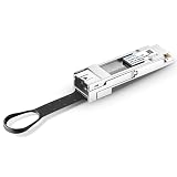
- This coverter supports 25G-SR, 25G-LR, 25G-ER, 25G-ZR, 25G SFP28 Copper Cable and 25G SFP28 Active Optical Cable.
- QSFP adapter module use SFP+ in QSFP+ port of your device. It allow connect to a lower-speed port on the other end of the network with low insertion loss and crosstalk.
- Tested in targeted switches for superior performance, quality, and reliability. A cost-effective offers 10 gigabit ethernet connectivity for only QSFP port equipment.
- This QSFP converter can be used for longer transmission distances than QSFP breakout cable.
- QSFP+ MSA form factor, plug and play. Max. power consumption 1.5W without module
InfiniBand
InfiniBand is an option for cluster interconnects in designs that provide the appropriate adapters, switches, cabling, management, and software. NVIDIA’s certification guidance describes multi-node clustering with InfiniBand or RoCE and emphasizes prescriptive certified configurations. Follow the exact certified topology and firmware matrix for the server you are deploying.
NVLink and NVSwitch
NVLink is a proprietary NVIDIA scale-up interconnect used inside supported systems. It is not a generic substitute for a tenant or management Ethernet cable. Where the MGX implementation includes NVLink or NVSwitch hardware, use the vendor’s specified internal connections and treat external network selection separately.
Independent reader supportYour contribution helps us test, update, and keep practical guides available for everyone.Use reference-design figures as examples, not a shopping list
NVIDIA’s NCP documentation shows why two nearby systems can need very different network components. In the cited reference tables:
| Reference tray | Tenant-access links | Cluster links | Scope |
|---|---|---|---|
| GB200 | Two 400GbE BF3 connections | Four 400Gb CX7 links configurable to InfiniBand or Ethernet | NCP GB200 reference design only |
| GB300 | One 400GbE BF3 configured as two 200GbE links | Four 800Gb CX8 links configurable to InfiniBand or Ethernet | NCP GB300 reference design only |
These counts and rates illustrate configuration variation. They do not define the ports on a Grace CPU SuperChip, GH200, or any other MGX server. Buy only the links required by the exact tray, switch topology, and certified deployment design.
Crashes, No Sound, or Screen Glitches?
Random freezes, missing sound and display glitches usually trace back to one bad driver. Find and replace yours safely.Free scan · under a minutePC Slower Than It Used to Be?
A free scan shows the junk files, broken settings and background clutter dragging Windows down - then fixes them in one click.Free scan · Windows 10 & 11A practical procurement workflow
- Freeze the server identity. Record chassis, board, accelerator, NIC model, firmware baseline, and vendor configuration number.
- Draw the traffic map. Mark host or tenant, BMC, cluster, storage, and any internal scale-up paths separately.
- Obtain switch-port assignments. For every destination, record switch model, port speed, connector, breakout state, and fabric protocol.
- Build a port-to-port matrix. List server port, intermediate optic or adapter, cable, switch port, lane mode, and required firmware or driver setting.
- Validate power with the facility. Match every PSU to a documented PDU outlet and circuit, including the desired redundancy arrangement.
- Check vendor compatibility lists. Confirm optics, transceivers, direct-attach cables, adapters, and firmware versions for both the server NIC and switch.
- Order spares strategically. Keep spare cables or transceivers only after the supported part number and failure-replacement procedure are known; do not substitute visually similar parts.
- Commission in stages. Test power and BMC first, then host access, then cluster links. Record negotiated speed, lane state, errors, and switch telemetry.
Troubleshoot the most common selection failures
No link after installing a cable
Check the connector and lane mode at both ends, then confirm that the optic or transceiver is supported by both devices. Read the NIC and switch diagnostics for unsupported module, lane mismatch, or administratively disabled port messages. A cable rated for a higher nominal speed does not guarantee operation at a lower speed unless both endpoints document that mode.
Best Value

- 40GbE QSFP+ to 4xSFP+ DAC Direct Attach Copper Twinax Breakout Cable, Passive, 1-Meter(3.3ft), 30AWG
- Widely compatible with Cisco QSFP-4SFP10G-CU1M Devices, and other open switch Devices
- 40G QSFP+ to 4xSFP+ Cable can connect 40 Gigabit switch, router, server, NIC, or other fiber optic equipments with QSFP+ ports to 10 Gigabit equipments with SFP+ port for Network Attached Storage, Storage Area Network, and High Performance Computing
- In 10Gtek's Signal Integrity Lab, we 100% passed TDR & VNA tested. And each DAC Cable is individually tested on switches before delivery
QSFP-to-RJ45 conversion does not work on a GH200
Verify that the ConnectX-7 is still in QSFP mode, that the adapter and SFP-to-RJ45 transceiver are installed in the intended order, and that the switch port matches the transceiver speed. If the hardware chain is correct, perform the documented OS-level firmware change to Ethernet mode. Do not assume that inserting the adapter changes firmware behavior.
BMC is unreachable while host traffic works
Confirm that the cable is connected to the dedicated BMC RJ45 port, not a host NIC port. Check the management switch VLAN or physical segment, BMC address assignment, link status, and access-control rules. The host network can be healthy while the BMC path is disconnected or isolated.
One PSU reports a fault
Check that the inlet is fully seated and that its PDU circuit is energized. Compare the live PDU reading with the vendor’s documented input requirements. If the system requires multiple supplies for operation or redundancy, do not remove another cable to “balance” the rack without vendor and facility approval.
Links flap under load
Inspect cable routing and bend radius, confirm transceiver temperature and coding, and compare error counters at both endpoints. Verify that FEC, MTU, breakout, and congestion settings match the selected fabric. Replace components only with parts listed as supported for that exact NIC and switch combination.
Final decision checklist
- Exact MGX server and vendor configuration are identified.
- Power cable count, connector, input rating, PSU quantity, and redundancy come from that configuration’s documentation.
- Facility voltage, phase, PDU receptacles, circuit capacity, and cable routing are approved.
- Host, BMC, tenant, cluster, and internal scale-up roles are separated.
- Fabric choice is tied to the workload and certified topology.
- NIC, switch, transceiver, cable, connector, lane mode, and speed match end to end.
- GH200 ConnectX-7 installations account for dual QSFP+ ports and the OS-level firmware change required for Ethernet mode.
- Reference-design port counts are not being reused as universal MGX requirements.
- Commissioning tests cover power status, BMC reachability, negotiated link state, and error counters.
The responsible way to choose MGX components is therefore a configuration-matching exercise, not a generic shopping list. Use the Grace CPU SuperChip and GH200 details as documented examples, then replace them with the exact server vendor’s electrical and networking requirements before placing an order.
Quick Recap
Product prices and availability are accurate as of the date/time indicated and are subject to change. Any price and availability information displayed on Amazon at the time of purchase will apply.

