Do these 3 things before closing this tab:
1Scan for outdated or missing drivers - takes under a minute2Clear out junk files and repair common Windows errors3Fix the driver behind crashes, sound loss and screen glitchesThe reliable way to make a custom Steam Frame accessory is to treat it as a small engineering project: begin with the latest Frame CAD, design around cameras, tracking hardware, controls and adjustment travel, select a filament for the part’s actual job, print a cheap interface prototype, and test that prototype on your own headset. A CAD match is only a starting point; it does not prove that a part is comfortable, removable, durable or safe. No Steam Frame accessory was physically tested for this guide.
What you need to design around
Valve describes Steam Frame as a wireless VR headset with a modular head strap. The core module can be separated for other strap solutions, which creates opportunities for brackets, cable guides, counterweight mounts, protective covers and other add-ons. It also creates several ways for a seemingly simple part to interfere with tracking or fit.
As an Amazon Associate I earn from qualifying purchases.
| Published detail | Value and qualification |
|---|---|
| Core module plus facial interface dimensions | 175 × 95 × 110 mm, listed by Valve in 2026. Valve notes that some specifications may change before availability. |
| Weight with strap | 440 g, according to Valve’s 2026 product information. |
| Core-module weight | 185 g, according to Valve’s 2026 product information. |
| Target interpupillary-distance range | 60–70 mm. |
| Maximum glasses width | 140 mm. |
| Outward-facing tracking cameras | Four monochrome cameras for headset and controller tracking. |
| Interior cameras | Two cameras for eye tracking and foveated streaming. |
| Expansion access | A user-accessible front expansion port. |
Use those figures as envelope and user-interface constraints, not as a promise that a printed facial interface will fit every face or eyewear setup. A part that stays inside the overall bounding box can still press on the wrong surface, narrow eye relief, block a camera, or prevent the strap from moving.
Find and verify the right CAD
Use Frame-specific files
A Hackaday report by Donald Papp, published October 10, 2026, says Valve’s hardware-reference repository includes STEP models for the Steam Frame core module, head strap and controllers, along with the locations of controller infrared tracking LEDs. STEP is useful because it preserves solid geometry that can be measured and referenced in a mechanical CAD program. The report’s quoted description is that the repository contains “STEP format models of the VR core module, head strap, and controllers, so it’s as easy as possible to design things that’ll fit.”
#1 Best Overall
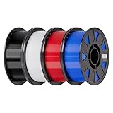
- Ender PETG Filament - combines the advantages of PLA and ABS, offering an eco-friendly, odorless, and user-friendly 3D printing experience. It features enhanced toughness that effectively resists cracking and warping, ensuring smooth and successful prints.
- Excellent Mechanical Properties - This PETG filament boasts high strength, impact resistance, and temperature resistance, with low shrinkage and high elongation at break. Printed models remain sturdy and durable even under repeated bending or stress.
- High Clarity & Glossy Finish - It delivers outstanding transparency and light transmission, making it perfect for visually detailed projects such as lampshades and display cases. The surface finishes with a smooth, glossy appearance.
- Reliable Printing & Compatibility - Dried, vacuum-sealed, and tangle-free, it minimizes clogging, bubbling, and snapping. With a precise diameter of 1.75mm (±0.02mm), it feeds smoothly and is compatible with most FDM printers on the market.
- Safe and Supported - Non-toxic and chemically resistant, Ender-PETG is safe for everyday use. Backed by Creality’s 12-month & 24 hours after-sales service. Note: Please place this product in a dry and ventilated environment, not in an environment of high temperature, sunny or humid conditions.
The repository itself was not accessible during preparation of this article. Check Valve’s live repository, file revisions and license before downloading, modifying or distributing anything. The license and precise Frame-specific exclusion geometries should be treated as unverified until you inspect the current files yourself. Do not assume that a file mentioned in a secondary report is still current.
Confirm units, orientation and revision
Before modeling, open the STEP assembly in your CAD application and verify that the units are millimetres. Identify the revision or commit associated with each file, then record it in your project notes. Check which surfaces represent the real mating surfaces rather than cosmetic shells, and establish a fixed coordinate system. A wrong import scale or a mirrored controller model can produce a part that looks correct on screen but cannot be installed.
Do not substitute Index geometry
Valve’s publicly accessible Index CAD documentation offers useful design habits, such as preserving capacitive input surfaces and sensor clearances and avoiding shiny or reflective surfaces outside a sensor inclusion zone. Those instructions are Index-specific. They are not evidence of Steam Frame geometry or of Steam Frame sensor tolerances. Use the Frame files for every Frame accessory, and use Index guidance only as general caution where it is clearly labeled as such.
The Tool Desk
Outbyte Driver Updater FREEFix the driver behind crashes, sound loss and screen glitchesFind Drivers →Outbyte PC Repair FREERepair Windows errors before they cause bigger problemsFix Now →A disciplined design-to-print workflow
1. Define the job and the failure you will not accept
Write a one-sentence specification before drawing. Examples include: “A removable battery bracket that does not touch any camera and can be detached without tools,” or “A flexible bumper that absorbs table contact without changing eye relief.” Decide whether the part is structural, protective, flexible, cosmetic or merely a shape mock-up. List unacceptable outcomes, such as blocked tracking, pressure on the face, loss of a control, strap restriction, sharp edges or a need to force the part into place.
2. Mark exclusion zones from the current model
Create construction geometry around every camera opening, controller infrared LED path, button, analog input, capacitive surface, charging or data access point, strap pivot and expansion interface. Keep these as named keep-out volumes in the CAD file so later edits cannot accidentally fill them. The four outward monochrome cameras, two interior eye-tracking cameras and front expansion port are product-level constraints; the exact boundaries and angles must come from the current Frame models and your own inspection.
Rank #2

- ①【PETG Filament 1.75mm】SUNLU PETG 3D Printer Filament combines the advantages of both PLA and ABS 3D printer filament, making 3D printing more convenient and easy.
- ②【Excellent Layer Adhesion】PETG filament offers excellent layer adhesion, reducing the risks of warping and ensuring smooth, strong prints with great structural integrity.
- ③【Enhanced Toughness】Known for its toughness, PETG outperforms many other filaments in durability, making it ideal for creating sturdy and resilient items that can withstand stress and use.
- ④ 【High Impact & Mechanical Strength】Stronger than standard PLA and easier to print than ABS. Our PETG filament provides excellent layer adhesion and impact resistance, preventing warping or cracking under stress. Perfect for printing functional parts, RC drone frames, or heavy-duty household tools.
- ⑤【Weather-Resistant for Outdoor Use】Engineered with robust UV and moisture resistance, SUNLU PETG maintains its structural integrity and color vibrancy over time. It is the ideal choice for outdoor planters, car accessories, and weatherproof garden fixtures that endure harsh sunlight or rain.
3. Reference the actual mating surface
Build the accessory from the surface that will touch the headset, strap or controller, not from an external silhouette. Add a deliberate clearance instead of relying on a coincident CAD face. Account for print tolerance, layer ridges, support scars, paint or tape, and any soft pad you intend to add. If the part wraps around a shell, split it into sections so removal does not require levering against lenses, buttons or the facial interface.
4. Make adjustment and removal part of the model
Model the full range of strap movement, hinge travel, eye-relief adjustment and any user-installed expansion hardware. A bracket that fits in one position may stop the strap from tightening or make the headset impossible to remove. Add finger access to clips and fasteners. Prefer captive features, broad contact pads and generous edge radii over thin hooks that concentrate force.
Free tools Windows power users keep installed
One-click scans. No signup required.
5. Print an interface coupon first
Do not begin with a full decorative shell. Print only the mating ring, one clip, a camera-clearance section or a short length of the proposed strap interface. Use inexpensive material and the same orientation, layer height and support strategy planned for the final part. Measure the coupon with calipers, inspect the contact face and make a controlled dimensional change. Record what changed and why; avoid sanding or forcing a bad fit until you have identified the underlying error.
6. Add retention without trapping the headset
Choose retention that fails gently. A part should release before it damages the headset if it is pulled, twisted or snagged. Avoid adhesive on device surfaces unless the manufacturer explicitly permits it. If using screws, keep their length and heads away from electronics, lenses and skin-contact areas. For a strap-mounted component, check that tightening the strap does not turn the accessory into a pressure point.
7. Prepare the production print
Orient layers so the main loads do not split the part along a weak layer boundary. Use manufacturer-recommended profiles for the exact filament and printer rather than copying a temperature from another machine. Design chamfers and support interfaces where they can be cleaned without changing the mating geometry. Label the part with a revision or date in a hidden area so you can identify which version was tested.
Rank #3

- ①【PETG Filament 1.75mm】SUNLU PETG 3D Printer Filament combines the advantages of both PLA and ABS 3D printer filament, making 3D printing more convenient and easy.
- ②【Excellent Layer Adhesion】PETG filament offers excellent layer adhesion, reducing the risks of warping and ensuring smooth, strong prints with great structural integrity.
- ③【Enhanced Toughness】Known for its toughness, PETG outperforms many other filaments in durability, making it ideal for creating sturdy and resilient items that can withstand stress and use.
- ④【High Impact Strength】With its high impact resistance, PETG is perfect for printing parts that need to endure bumps and drops, ensuring long-lasting performance without cracks or breaks.
- ⑤【Robust Durability】PETG prints are robust and maintain their properties over time, making them suitable for both indoor and outdoor applications where weather resistance is a necessity.
8. Inspect before installation
Look for warping, cracks, incomplete walls, blobs, stringing, elephant-foot deformation, lifted corners and support scars. Check every critical dimension and run a finger over edges that might touch the face, strap or headset shell. Remove support material completely from clips and camera openings. A visually attractive part with a distorted mating face is not ready for use.
Quick wins for a faster PC:
Clear out junk files and repair common Windows errorsFree Scan →Fix the driver behind crashes, sound loss and screen glitchesFind Drivers →Choose filament by function and printer
There is no single best filament for all Steam Frame accessories. PETG, ASA, flexible TPU or TPE, and PLA solve different problems, and filament brands and blends vary. Neither Valve nor Prusa certifies these materials for Steam Frame accessories.
| Material | Good candidate uses | Advantages | Trade-offs and cautions |
|---|---|---|---|
| PETG | Functional prototypes, holders, clamps and brackets with moderate mechanical demand. | Prusa characterizes it as tenacious, with good layer adhesion, low warping and useful toughness for mechanical parts. | Stringing, weaker bridges and overhangs, support-removal difficulty and less fine detail than PLA can affect fit. Use the profile for your particular printer and filament. |
| ASA | Parts exposed to ultraviolet light or higher temperatures, such as an outdoor stand or a component near a warm enclosure. | Prusa reports resistance up to 93 °C and recommends ASA for technical and outdoor use. | Significant warping and potentially harmful fumes make it more demanding. Ventilation is required, and larger prints benefit from an enclosure. The 93 °C figure is material-guide information, not a Steam Frame operating limit. |
| TPU/TPE | A deliberately compliant bumper, vibration damper or flexible strap-related feature. | Flexible materials are tenacious and can conform to a contact surface. | They are comparatively difficult to print and require a printer capable of handling flexible filament. Excess flexibility can let an accessory shift or obstruct a sensor. |
| PLA | Low-cost shape prototypes that will not carry load or see substantial heat. | Usually the lowest-barrier route for checking shape and clearance. | Do not treat PLA as universally unsafe or universally suitable. Verify the intended environment and the specific filament’s properties before using it for a working part. |
PETG for most first functional prototypes
PETG is often a practical starting point for a rigid bracket or holder because its toughness and layer adhesion can tolerate ordinary handling. Plan for strings around posts and openings, and inspect bridges and overhangs that define a camera window or clip. If a support scar changes a mating face, reprint or machine the surface rather than tightening the fit by force.
ASA when exposure justifies the extra difficulty
Choose ASA for a defined ultraviolet or temperature requirement, not simply because its headline temperature resistance sounds stronger. Warping can change a long shell enough to move a camera opening or make a clip uneven. Print with the ventilation and enclosure your printer and local safety practice require, and keep fumes away from occupied rooms.
Flexible materials only where movement is intentional
A TPU or TPE bumper should have a specified compression or deflection role. If the entire mount is flexible, the headset can move relative to the accessory and tracking or controls may become unreliable. Use a rigid carrier with a small compliant pad when only the contact interface needs to yield.
What’s actually slowing this PC down?
Pick the symptom - the matching free tool is one click away.
Rank #4

- [Excellent PETG Filament]Our PETG combines the benefits of PLA and ABS to reach Eco-friendly and odorless performance. This PETG Filament is feature in good toughness to avoid cracking and warping, enbale excellent 3D printing.
- [Toughness-enhanced PETG] Our PETG filament choose durable and strong material that delivers excellent clarity, light transmission, and a glossy finish. It is recommended to use a printing temperature of 220-250°C and a base plate temperature of 70-80°C for better printing results.
- [Tangle-Free & Neatly Wound] We ensure that every PETG filament is tightly and neatly wrapped by utilizing full mechanical winding, which effectively minimizes tangles, filament snapping, and line breakage.
- [No Clogging & No Bubbles] Our filaments are thoroughly dried and carefully vacuum sealed to protect them from moisture and dust, which ensures that there will be no issues with clogging or bubbling during printing. Our PETG is designed to be perfectly compatible with the majority of 1.75mm FDM 3D printers, especially suitable for Creality 3D Printers!
- [High Precision & Consistent Performance]Our PETG filament boasts a diameter of 1.75mm, ensuring utmost accuracy with a tolerance of only +/- 0.03mm. With strict quality control and impeccable dimensional precision, our PETG filament guarantees a smooth and steady feeding during printing.
Accessory concepts and their specific constraints
Camera guards and protective frames
Keep the guard outside each camera’s field of view, not merely outside the visible lens opening. Thin ribs can still intrude at an angle. Leave enough clearance for cleaning and for the camera housing’s edges. A guard should break away or release under impact rather than transfer a sharp load into the headset shell.
Strap adapters and counterweight mounts
Use the strap CAD to locate attachment points and model the strap at its loosest and tightest settings. Counterweights alter the load on the user’s head and may change comfort even when the accessory is mechanically secure. Keep the weight close to the intended support structure, provide a tool-free removal path, and check that tightening the strap does not pinch the user.
Controller grips and shells
Preserve every button, analog input and capacitive surface. Ensure controller infrared LED paths remain visible to the headset. Do not use glossy or reflective finishes in areas where they could create tracking reflections; the older Index guidance is a caution, not a Frame-specific measurement. Keep the grip removable so battery or charging access is not sacrificed.
Front-port covers and expansion mounts
The front expansion port is user-accessible, so a cover or mount must not block insertion, removal or cable bend radius. Add a tether or flexible door only if it cannot swing into a camera view or control. Test with the actual cable or expansion hardware, not a dimensionally idealized placeholder.
Facial-interface accessories
Any facial-contact part has a higher burden of proof. Maintain eye relief and the user’s natural field of view, avoid pressure ridges, and design surfaces that can be cleaned. A printed facial interface must be checked with the user’s own glasses and face shape; the 60–70 mm target IPD and 140 mm maximum glasses width are headset specifications, not a guarantee for a custom cushion or frame.
Best Value

- High Performance & Strength: PETG filament combines the strengths of PLA and ABS. It offers low shrinkage, high impact resistance, excellent temperature resistance, and high elongation at break, models can bend repeatedly and remain firm and sturdy
- High Transparent & Glossy: PETG has a high degree of transparency. The finished product has a fine surface with exquisite details. This makes PETG material ideal for making transparent parts and models, such as lampshades, display boxes, and more
- Non-toxic Material: Creality CR-PETG 3D printing filament has excellent wether resistance and chemical resistance, no odor, and non-toxic, green environmental protection
- Wide Compatible: CR-PETG filament is wildly used in FDM 3D printers on the market.Compatible with most popular 3D printers such as MK3, Creality Ender series/CR series, ELEGOO, Anycubic, and more
- Creality Support: Creality provides 12-month & 24 hours after-sales service. Note: Please place this product in a dry and ventilated environment, not in an environment of high temperature, sunny or humid conditions
Printing and post-processing checks
- Use a clean, level build surface and the filament maker’s drying and storage guidance.
- Measure the first layer and any critical hole, slot, clip or mating face after cooling.
- Remove strings and supports without widening openings or thinning retention tabs.
- Round or chamfer hand-contact edges; inspect for burrs and sharp layer artifacts.
- Do not polish, paint or coat a sensor-facing surface until you have confirmed that the finish cannot affect tracking or camera visibility.
- Keep a versioned record of filament, printer, profile, orientation and post-processing so a successful fit can be reproduced.
Prusa’s material guidance emphasizes that print defects and material differences affect the finished part. A clean visual inspection is not a substitute for dimensional measurement, especially on clips and interfaces that determine whether force reaches the headset.
Test the part on the actual headset
These checks are a conservative maker workflow, not a Valve-certified protocol or a reported hands-on test. Perform them in a clear area, with the headset powered off where practical, and stop immediately if a part requires force or causes discomfort.
- Dry fit: Place the accessory without fully engaging its retention. Confirm that no edge touches a lens, facial interface, camera window, strap pivot or control.
- Attach and remove: Complete the installation, then remove it using the intended path. There should be no levering against the headset and no need to flex a rigid shell beyond its design.
- Check controls and access: Operate every button, analog input and capacitive surface. Open charging, data and expansion access as applicable.
- Check cameras and tracking: Inspect all four outward-facing monochrome camera views and both interior eye-tracking camera areas for obstruction. In software, verify headset and controller tracking before moving on.
- Check fit and comfort: Wear the headset with your normal strap adjustment and eyewear. Look for pressure points, changed eye relief, reduced view, wobble or contact that appears only after tightening.
- Check adjustment range: Move the strap through its useful range and make the normal eye-relief or fit adjustments. The accessory must not stop or pinch those movements.
- Check ordinary handling: Turn, lift and set down the headset as you normally would. Watch for shifting, rattling or a clip that slowly backs out.
- Reinspect: Remove the part and look for whitening, cracks, polished rub marks or deformed tabs. Recheck the headset for scratches or pressure marks.
Stop using the accessory if it obstructs a sensor, shifts during use, causes discomfort or requires force to attach or remove. Modify the CAD and print a new revision instead of compensating by bending, wedging or gluing the part in place.
Troubleshoot by symptom
| Symptom | Likely causes | Corrective action |
|---|---|---|
| Clip will not seat | Warped print, incorrect scale, support residue or an undersized clearance. | Measure the mating features, verify units and revision, flatten or reprint the interface and increase clearance only in the constrained direction. |
| Part fits but shifts in use | Insufficient retention, excessive flexible material or load placed far from the mount. | Move the load closer to the attachment, add a broad compliant pad or redesign the retention. Do not simply increase clamp force against the headset. |
| Tracking becomes unreliable | A rib, wall, cable or shiny surface enters a camera or infrared LED path. | Remove material from the keep-out volume, verify the view at several head angles and use a non-reflective finish where appropriate. |
| Strap cannot tighten or release | The accessory occupies the strap’s travel or blocks finger access. | Model both end positions, move the mount outside the travel envelope and add a tool-free release path. |
| Face pressure or reduced view | Contact pad is too narrow, eye relief changed or the part conflicts with glasses. | Increase contact area, add a compliant interface, restore the original adjustment range and retest with the user’s eyewear. |
| Long print is bowed | Material shrinkage, bed adhesion or enclosure conditions, particularly with ASA. | Follow the material’s enclosure and ventilation guidance, improve bed preparation and redesign the part into shorter sections if necessary. |
Sharing, labeling and compatibility claims
Valve identifies products carrying the Steam Frame Compatible mark as accessories tested to work with the headset. That mark is distinct from a maker’s own fit check. Do not describe a home-printed part as officially compatible, safe, certified or endorsed unless you have actual authorization and supporting testing. Valve’s branding guidance also cautions against using the Steam Compatible mark in a way that suggests third-party endorsement.
If you publish files, include the Frame CAD revision you used, your printer and material, known limitations, installation and removal instructions, and the tests you performed. Check the live Valve repository license before redistributing derivative CAD or selling prints. A clear statement that users must inspect their own headset and stop if tracking, controls or comfort are affected is more useful than a broad fit guarantee.
What a finished project should prove
A finished accessory should have a traceable CAD reference, a material chosen for its actual environment, measured critical dimensions, clean contact surfaces and a documented test on the intended headset. The strongest evidence is not that the part looks close in a viewer; it is that the installed revision leaves cameras, eye tracking, controls, expansion access and adjustment travel usable, can be removed without force, and remains comfortable during ordinary handling. Treat every new filament, printer, headset revision or user fit as a new combination that deserves its own check.
Quick Recap
Product prices and availability are accurate as of the date/time indicated and are subject to change. Any price and availability information displayed on Amazon at the time of purchase will apply.

