Researchers grow nerve pathways on a chip by placing neurons in separate fluidic compartments and giving their axons a narrow physical route between them. In the foundational compartmentalized design, cell bodies remain in one chamber while axons extend through micrometer-scale grooves into another. This arrangement makes a selected connection visible, treatable and measurable without trying to recreate an entire brain.
The result is an in-vitro engineered model, not a miniature brain. Its value comes from controlling geometry, cell populations, chemical exposure and measurements tightly enough to ask questions that are difficult to isolate in a conventional dish.
As an Amazon Associate I earn from qualifying purchases.
What a nerve-pathway chip actually is
A neural microfluidic chip is a transparent culture device divided into two or more chambers. One chamber usually holds neuronal cell bodies (somas); another receives the axons that grow away from them. Narrow microchannels or grooves in the barrier connect the regions. The dimensions restrict where cells can move while permitting axons to pass, so researchers can examine a pathway rather than an undirected sheet of cells.
The physical partition preserves access to each population. Scientists can image the soma compartment, collect material from the axon side, or expose only one region to a soluble compound. Depending on the design, the connected cells may come from one population, different neuronal types, or distinct brain regions. Devices can also be arranged to encourage one-way orientation, isolate axons in dedicated channels, or form two-dimensional and three-dimensional circuits.
#1 Best Overall

- Standard matched fittings, perfect fit most common PDMS microfluidic chips set.
- Stable sealing performance, Practical integrated design, meet daily microscale fluid testing needs.
- Do not push samples into the chip manually. Under normal use, keep pressure ≤ 2 bar and maximum flow rate ≤ 2 ml/min. Exceeding these parameters will cause permanent damage to the chip.
“Brain-on-a-chip” is an umbrella term. It can describe a simple two-dimensional compartment system or a substantially more complex three-dimensional culture containing neurons, glia, barriers and electrodes. The name alone does not tell you how closely a model represents brain tissue.
How do you grow nerve pathways on a chip?
The best-known basic workflow comes from the 2006 Nature Protocols method associated with Park and colleagues. It uses replica-molded, transparent polymer parts to form a multi-compartment culture platform. The exact dimensions and surface treatment are protocol-specific, but the sequence is broadly understandable.
- Make the patterned device. A mold defines the chambers, microchannels and the barrier grooves. Polymer parts are molded and assembled into a transparent chip that permits microscopy.
- Prepare the culture surfaces. The channels and chambers are treated so neurons can attach and extend processes. Surface chemistry matters: attachment and outgrowth depend on the coating and the cell preparation.
- Seed neurons in the soma compartment. Cells are introduced into the chamber intended to retain their bodies. The channel geometry is chosen so whole cells do not readily cross the barrier while axons can.
- Allow axons to extend. In the cited protocol, neurons seeded in the soma side have axons crossing the grooves after about three to four days in vitro. That timing is a protocol result, not a universal maturation schedule for every cell type or device.
- Establish fluidic separation when needed. A small hydrostatic pressure difference between compartments can limit mixing. After a medium change, an investigator can then apply a soluble insult or treatment to one side while leaving the connected region as a comparison.
- Verify the connection before testing. Microscopy is used to confirm axons in the channels and to check that the intended compartments remain populated and separated. Experiments should define in advance what counts as a usable connection.
The fabrication and setup portion of this foundational method is reported as achievable in roughly one to two days. That is separate from the three-to-four-day period needed for axonal crossing and from any longer maturation or disease-modeling period.
How can a chip guide axons?
Guidance is primarily physical. A barrier with micrometer-sized grooves creates a low-width route that favors axonal extension over movement of neuronal cell bodies. Longer microchannels can keep axons in an optically accessible corridor, making it possible to image transport, branching or injury along a defined path.
Geometry can also impose directionality. Separate entry and exit regions, channel length, turns and constrictions influence which processes reach another compartment. The 2022 review of neural-circuit engineering describes combining physical confinement with neuro-adhesive materials and other design choices. In practice, the device architecture and the biological coating work together: a channel that is geometrically suitable may still fail if cells do not attach or extend reliably on its surface.
Rank #2

- Replacement accessory kit for microfluidic chips includes PTFE tubing, blunt needles, needle tips, syringes and syringe filters in one package
- PTFE tubing 0.7 meter, ID 0.5mm, OD 1.0mm, fits standard 22G microfluidic fittings and 0.7mm chip inlet and outlet ports
- Six 22G stainless steel blunt needles and three needle tips connect syringes to tubing with luer-lock fittings for secure fluid delivery
- Three 2mL luer-lock syringes and three 0.22 micrometer PES syringe filters for sample loading and filtration before chip injection
- Works with LabCore Materials microfluidic chips and other standard PDMS or glass microfluidic devices for research use only
Some platforms use several connected compartments rather than a simple two-chamber arrangement. This allows a researcher to represent a chain of populations, place a target region downstream, or compare axonal and somatic responses separately. Other designs embed the channels in a three-dimensional matrix, trading the clean separation of a two-dimensional layout for a tissue-like environment.
What is a brain-on-a-chip used for?
Localized exposure and injury studies
Compartmentalization lets investigators apply a chemical, inflammatory signal or other soluble challenge to one region and observe effects in the connected region. Because the treatment is localized, a change in the axon compartment can be distinguished from a direct change in cell bodies. Fluidic isolation is essential when the question depends on keeping the solutions different; without it, diffusion can erase the intended contrast.
Recommended Free Tools
Connectivity and communication
A chip can test whether two selected populations form a physical and functional connection under defined conditions. The approach is more controlled than mixing all cells in one well, where the source and destination of a process may be ambiguous.
Organotypic brain-region models
Berdichevsky, Staley and Yarmush reported an organotypic platform in which cortex and hippocampus slices formed functional connections through microchannels. Their system showed synchronized activity and allowed selective pharmacological manipulation of the constituent slices. That finding applies to the reported cortex–hippocampus design; it should not be generalized to every neural chip or every pair of cultured regions.
Neuroinflammation and neurodegeneration models
More elaborate systems add multiple human cell types and three-dimensional organization. A 2023 protocol describes a 3D human multicellular culture intended for controlled neuron–glia interactions and disease conditions, including neuroinflammation and neurodegeneration. Such a model can ask how glial signals, neuronal activity and tissue architecture interact, rather than treating neurons as an isolated population.
Rank #3

- Standard matched fittings, perfect fit most common PDMS microfluidic chips set.
- Stable sealing performance, Practical integrated design, meet daily microscale fluid testing needs.
- Do not push samples into the chip manually. Under normal use, keep pressure ≤ 2 bar and maximum flow rate ≤ 2 ml/min. Exceeding these parameters will cause permanent damage to the chip.
Barrier and circuit engineering
The 2024 review of microfluidic and semiconductor technologies covers in-vitro blood–brain-barrier models, neuronal circuits, three-dimensional tissue engineering and electrode strategies for recording activity. These platforms combine biology with fluid handling, materials and electronics. A chip is useful only when those components match the biological question and the required readout.
Free tools Windows power users keep installed
One-click scans. No signup required.
Choosing between common model designs
There is no universally best brain-on-a-chip format. Compare a proposed design against the question, the cells available and the measurement you need.
| Decision axis | 2D compartmentalized culture | 3D multicellular model |
|---|---|---|
| Organization | Flat chambers linked by grooves or microchannels; straightforward separation of somas and axons | Cells embedded or assembled in a three-dimensional environment; more tissue-like spatial relationships |
| Cell populations | Often one population, or two deliberately paired populations; organotypic slices are also possible | Can combine human neurons, glia and other cells in a defined multicellular model |
| Axon control | Strong control over channel position, direction and axon isolation | Guidance depends on the 3D matrix and architecture; the exact degree of isolation is design-specific |
| Localized treatment | Separate chambers can be fluidically isolated for one-sided exposure | Possible, but transport through a 3D matrix and the device plumbing must be characterized |
| Typical readouts | Microscopy, compartment-specific biochemical sampling and, in some systems, electrical activity | Microscopy, molecular assays, activity measurements and neuron–glia or barrier responses |
| Timing and expertise | The 2006 platform reports one to two days for fabrication and setup, with axons crossing after about three to four days in vitro | The cited 2023 workflow reports two days to set up, one to nine weeks to develop models and two to three days for analyses; it calls for at least one month of training for researchers with basic molecular-biology experience |
The timings in the table belong to the cited protocols. They are not promises for every cell source, coating, chip geometry or disease model.
What should be measured?
Microscopy
Fluorescence imaging can show neuronal bodies, axons in the connecting grooves, branching and damage after treatment. Time-lapse imaging can follow extension, transport or degeneration along a defined route. A clear imaging plan should specify whether the endpoint is the number of connected channels, axon length, signal intensity, branching or another measurable feature.
Compartment-specific molecular analysis
Separate chambers make it possible to collect medium or cellular material from the soma and axon sides independently. This can reveal whether a treatment changes a local signal before a downstream region responds. Controls must account for unequal volumes, evaporation and any residual mixing between compartments.
Rank #4

- Double herringbone microchannel design enhances passive fluid mixing efficiency under laminar flow conditions, supporting stable and repeatable laboratory experiments.
- PDMS microfluidic chip features high optical transparency and flexible sealing performance, making it suitable for microscopy observation and laboratory research.
- Compatible with syringe pumps, laboratory tubing systems and common microfluidic accessories for fluid handling, chip testing and experimental development.
- Suitable for microfluidic research, liposome preparation, nanoparticle studies, laboratory demonstrations and academic research applications.
Electrical activity
Some devices incorporate electrodes or place the chip on an external recording system. Activity can be compared across connected populations, and synchronized signals can provide evidence of functional coupling. Electrical synchronization should be interpreted with the recording geometry and pharmacological controls in mind; a visible axon is not automatically a functional synapse.
Barrier and transport measurements
In blood–brain-barrier or perfused designs, researchers may measure permeability, flow-dependent responses and interactions between vascular and neural compartments. These experiments require characterization of fluid paths in addition to biological validation.
Planning a reliable experiment
- Start with the biological claim. Decide whether you need to show axon guidance, directional connectivity, a localized insult, neuron–glia interaction, barrier behavior or network activity. Do not select a device solely because it is marketed as a brain-on-a-chip.
- Choose the minimum model complexity. A two-dimensional compartment system may answer a localization question more clearly than a 3D model. Add cell types, regions or matrix complexity only when they address a defined limitation.
- Define the source and destination populations. Record species or human-cell source, developmental state, neuronal subtype and whether the model uses dissociated cells or organotypic tissue. These factors affect outgrowth and maturation.
- Validate physical separation. Demonstrate that somas remain where intended, that axons occupy the connecting channels and that fluidic isolation is adequate for a one-sided treatment.
- Build in functional controls. Include untreated connected cultures, treatment controls in each compartment and, when claiming communication, a control that interrupts or pharmacologically tests the connection.
- Match the endpoint to the timeline. Distinguish device setup, axonal crossing, maturation, treatment and analysis. A two-day fabrication schedule does not mean a disease model is ready in two days.
Common failure modes and how to interpret them
Axons do not enter the channels
Possible causes include unsuitable surface coating, low cell viability, incorrect channel dimensions or a cell type with a different growth requirement. Check attachment and outgrowth in a simple reference culture before changing the entire device design. Confirm that the grooves are open and free of bubbles.
Cell bodies cross the barrier
Cell migration can undermine compartment-specific treatment. Re-examine the barrier geometry, seeding density and handling steps. A design that permits whole-cell passage cannot support a strong claim that only axons connect the regions.
The Tool Desk
Outbyte Driver Updater FREEScan for outdated or missing drivers - takes under a minuteDriver Scan →Outbyte PC Repair FREEClear out junk files and repair common Windows errorsFree Scan →Treatments spread between compartments
Verify the hydrostatic pressure difference, liquid levels and seals. Trace-dye tests or equivalent fluid checks can reveal leaks before biological experiments. If the question requires a localized insult, measure cross-compartment contamination rather than assuming isolation.
Best Value
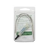
- The Fast Chip SMD Removal Kit is a quick and inexpensive way to remove SMD components from a PCB without a hot air station using only your soldering iron.
- Removes QFP's, PLCC's, SOIC's, and chip components under 300 degrees Fahrenheit
- Enough material to remove 8-10 SMD'S
- The Kit Contains: 2.7 ft. Fast Chip Removal Alloy - 1 2cc tube of SRA TF5000 No Clean Rework Paste Flux and complete Instructions for SMD Removal and Cleanup
- Lead Free
Visible connections produce no coordinated activity
Structural contact and functional communication are different endpoints. Allow appropriate maturation, verify cell health and use activity measurements and controls. The cortex–hippocampus result reported by Berdichevsky and colleagues demonstrates one functional platform, not a guaranteed outcome for another design.
The model is too complex to interpret
Three-dimensional multicellular systems can introduce gradients, transport limits and multiple interacting cell types. If a result cannot be assigned to a compartment, population or exposure, simplify the design or add measurements that resolve those variables.
How long does a nerve-pathway chip take?
There are several different clocks. The foundational 2D method reports one to two days to fabricate and set up the platform, then approximately three to four days in vitro for seeded neurons to extend axons through the grooves. That schedule describes a basic pathway configuration, not a fully matured disease experiment.
Quick wins for a faster PC:
Scan for outdated or missing drivers - takes under a minuteDriver Scan →Repair Windows errors before they cause bigger problemsFix Now →Fix the driver behind crashes, sound loss and screen glitchesFind Drivers →The cited 3D human protocol has a two-day setup, a one-to-nine-week model-development period and two-to-three days for analysis. It also specifies at least one month of training for researchers with basic molecular-biology experience. The longer timeline reflects multicellular development and disease-model preparation, not simply chip assembly.
In both cases, actual timing varies with cell source, coating, matrix, maturation target, imaging schedule and the acceptance criteria for a usable connection. Report those stages separately when planning a study or comparing results.
What these chips cannot tell you
A microfluidic neural culture removes much of the complexity of a living brain: full vascular and immune systems, long-range anatomy, changing endocrine signals, behavior and whole-organ feedback are not reproduced by a basic chip. Even a sophisticated 3D model represents selected mechanisms under controlled conditions.
Results therefore apply first to the cells, geometry, materials, flow conditions and readouts used in that experiment. A pathway chip can establish how a defined population responds when connected through a defined route; it cannot by itself establish how an intact human brain will respond.
What’s actually slowing this PC down?
Pick the symptom - the matching free tool is one click away.
The field is moving toward integrated circuits, barriers, 3D tissues and electrical interfaces, but added components do not automatically improve every study. The appropriate design is the one that makes the intended connection, exposure and measurement testable while keeping interpretation clear.
Quick Recap
Product prices and availability are accurate as of the date/time indicated and are subject to change. Any price and availability information displayed on Amazon at the time of purchase will apply.

