Free tools Windows power users keep installed
One-click scans. No signup required.
A probe card is the replaceable electrical interface between automated test equipment (ATE) and semiconductor dies that are still arranged on an intact wafer. The wafer prober holds and aligns the wafer, then moves its pads or bumps into the card’s probe tips. The tester sends patterns through the card into the die and measures the response returning through the same path. After one site is tested, the prober indexes the wafer to the next site.
The short version: three systems share the job
Wafer probing works because three separate systems perform different tasks. The ATE supplies test signals, timing, power and measurement electronics. The probe card converts the tester connection into many controlled contacts that can touch die electrodes. The wafer prober supports the wafer, aligns the contact pattern and controls the motion needed to make and release contact.

As an Amazon Associate I earn from qualifying purchases.
| System | Mechanical role | Electrical role |
|---|---|---|
| Automated test equipment (ATE) | Connects to the test setup rather than positioning the wafer | Drives test patterns and measures the die’s responses |
| Probe card | Provides the probe tips and mounting interface | Routes signals between tester channels and die pads or bumps |
| Wafer prober | Holds, aligns, raises and indexes the wafer | Does not perform the test logic; it enables repeatable contact |
| Wafer and die | Remain on the chuck during probing | Receive stimulus and return electrical responses through the contacts |
A useful mental model is ATE/tester electronics ⇄ probe-card wiring and probes ⇄ die pads or bumps, with the prober supplying alignment, support and controlled motion. The probe card is therefore not a tester and not a miniature test computer. It is the interface that makes electrical access possible while the die is still part of the wafer.
What happens from tester to die
-
Dies are fabricated in an array
Multiple semiconductor dies are built across a wafer. Before the wafer is cut into individual pieces and those pieces are packaged, each die can be contacted and screened in its wafer-level position.
#1 Best Overall
Sale TOZO A1 Wireless Earbuds Bluetooth 5.3 Light Weight in Ear Headphones | IPX5 Waterproof,2 Mics for AI Calls,Immersive Premium Sound Bass Headset with Charging Case,32 EQ via App Black
- [Ultra-Lightweight Ear Buds Designed for Small Ears] Each earbud weighs only 3.7g and features a compact, ergonomic in-ear design made especially for small ears. Secure, low-profile, and comfortable for workouts, all-day wear or overnight sleeping.The ultra-slim profile sits flush in your ear with no hard edges poking or rubbing, so you can even sleep on your side without discomfort.
- [Immersive Stereo Sound with TOZO OrigX Technology] TOZO OrigX tuning delivers clear vocals, balanced mids, and natural stereo sound for music, podcasts, and videos.
- [Long Battery Life for Daily Use] Get up to 7 hours of playtime on a single charge, with up to 32 hours total using the charging case—ideal for workdays, commuting, and extended listening sessions.
- [Bluetooth 5.3 & Stable Connection] Bluetooth 5.3 provides fast pairing, stable wireless performance, and reduced dropouts as you move around home or office.
- [Deep Bass with Clear Vocals] High-performance drivers produce punchy bass while keeping vocals clean and detailed for everyday listening.
-
The wafer is loaded onto the prober chuck
The prober holds the wafer on a chuck and establishes its position. The wafer must be oriented so the contact locations on the selected die correspond to the probe-card tip pattern. Optical alignment systems are used to locate wafer features and refine that registration.
-
The probe card is docked into the test setup
The card is mounted or docked between the tester-side electronics and the prober’s contact area. In supplier descriptions, it is the connector between LSI chip electrodes and an LSI tester, and the electrical and mechanical interface between the wafer device under test and the test-system electronics.
-
The prober brings the surfaces together
Once alignment is complete, the prober moves the wafer vertically or otherwise controls the approach until probe tips touch the selected die’s pads or bumps. Contact force and travel are controlled by the particular prober and card design; the objective is a stable electrical connection without damaging the wafer or the card.
Special offer. See more information about Outbyte and uninstall instructions. Please review EULA and Privacy policy. -
The ATE drives and measures
The tester applies its programmed signals through the card’s wiring and probes. Those signals reach the die electrodes, travel through the die’s circuits, and produce responses that return through the same contact interface to measurement channels in the ATE. The tester evaluates the responses against the test criteria, including functional or go/no-go decisions.
-
The wafer is indexed to the next site
After the selected site is released, the prober moves the wafer to the next die or test location and repeats alignment and contact. The number of sites contacted in one touchdown and the detailed sequence depend on the device, probe-card layout and test setup; a throughput figure from one product cannot be generalized to every wafer-probe system.
How the wafer prober makes contact repeatable
The prober is the motion-and-positioning half of the interface. It keeps the wafer flat and supported, establishes wafer coordinates, and brings the selected area toward the probe card. Its alignment task is critical because a small positional error can place tips between pads, off the intended bump, or at the wrong site.
Rank #2

- 【IP68 Waterproof Multifunctinal Smart Watch】Torjalph fitness activity tracker smart watch is IP68 waterproof technology ,you can wear it when swimming,handwashing,it's rain-proof which means that you perform multiple exercise modes outside without worrying about sweat or rain corroding your fitness smart watch,and this watch equipped with a 230 mAh large capacity battery magnetic charging ,and this sports activity tracker watch can be used 5-7 days If fully charged.
- 【Larger 1.83'' Full Screen Watch & Multi-dial Selection】1.83 inch full HD color touch screen smart watch for men / women provides excellent 240*284 resolution image quality ,This Bluetooth smart watch offers a better touch experience and remarkable immersion and ,more than 200 watch faces for you to choose from App"Da Fit ", you can change the dial style according to your mood to wear keeping the world on your wrist
- 【Accurate Activity Tracker Smart Watch 】sports watch activity tracker uses sweat and dust resistant breathable silicone strap, our Fitness Tracker Smart Watch for Android iOS Phones supports 12 sports modes,walking,running,bicycle,swimming,badminton,basketball,football,rope skipping. This bluetooth calls smart watch for men women is lightweight and stylish, bringing more convenient and relaxing sports experience while also providing more protection.
- 【Your 24 Hour Personal Daily Health Monitor】Fitness watch for women men full touch screen IP67 waterproof bluetooth smartwatch for Android iOS Phones with heart rate blood pressure monitor multifunction Andriod smart watch with steps counter sleep monitor sports fitness watch, monitoring blood oxygen saturation allows you to understand your physical condition in real time to track fitness progress ,to know your health status in time.
- 【More Functions Bluetooth Call Smart Watch】This fitness activity smart watch full screen for iPhone and Android phones includes a bunch of new features including:The bluetooth smart watch can hang up the phone, receive and display WhatsAPP /Text /Facebook /Twitter /Messenger reminder.Support sedentary reminder, alarm clock, stopwatch, timer,weather information,music control, remote camera control compatible with Android 5.0 and above or iOS 9.0 and above smartphones.
A typical contact cycle has four practical phases:
- Load and reference: the wafer is placed on the chuck and its orientation and reference features are located.
- Align: optical or other alignment functions map the wafer’s contact pattern to the card’s probe pattern.
- Touchdown: the stage moves the wafer into the probe tips so the intended electrodes are contacted.
- Separate and index: the stage releases contact, moves to the next coordinates and starts the next touchdown.
The card and prober must be treated as one mechanical system during setup. A card with the right electrical channels but the wrong pitch, tip arrangement or mechanical clearance will not contact the intended electrodes. Conversely, precise positioning cannot compensate for a card whose electrical path or contact structure is unsuitable for the test.
Do these 3 things before closing this tab:
1Repair Windows errors before they cause bigger problems2Fix the driver behind crashes, sound loss and screen glitches3Clear out junk files and repair common Windows errorsWhy probe dies before dicing and packaging?
Wafer probe testing is performed before dicing and packaging so manufacturers can electrically examine dies while they remain on the wafer. The test identifies devices that meet the criteria and flags devices that do not, before those dies continue through later production steps.
This stage is different from final package testing because the electrical access is made directly to wafer-level pads or bumps. The die has not yet been separated, placed in a package or connected to package leads. Wafer probing consequently requires a contact solution that can address the die’s layout in its as-fabricated position and then move efficiently across the wafer.
The result is a map or classification of tested sites that can guide subsequent manufacturing decisions. The available evidence supports functional and go/no-go screening at this stage, but it does not establish a universal yield percentage, cost saving or other numerical benefit.
Why probe-card designs vary
There is no single probe-card structure that fits every wafer. Designers match the contact technology to the die’s electrode geometry, pad or bump pitch, device type, signal-frequency requirements, desired parallelism and the way worn contacts will be maintained or replaced.
The Tool Desk
Outbyte PC Repair FREERepair Windows errors before they cause bigger problemsFix Now →Outbyte Driver Updater FREEFix the driver behind crashes, sound loss and screen glitchesFind Drivers →Cantilever cards
Cantilever cards are one established category. Japan Electronic Materials describes a cantilever construction in which probe wires are attached to an epoxy ring and associates that design with logic IC applications. The wires extend toward the die so their tips contact the electrode pattern during touchdown.
Rank #3
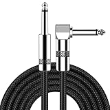
- [Low Noise High Fidelity] New bee guitar cord with 22AWG oxygen-free-copper center conductors provides enhanced signal transfer, the PVC insulation material and the high-density stranded copper double shield provide noise rejection for quiet operation
- [Ideal for Choice] New bee 1/4 straight and right angle metal connectors, ensures a secure connection in any instrument, pedal, or amp jack. L shape great fro on stage guitar stands
- [Wide Compatible] Suitable for mixer, power amplifier, microphone, effector, decoder, equalizer, electoronic organ, electric guitar, electric bass and other electronic equipments. Widely used in the installation of smart home, karaoke speaker, professional stage audio, etc
- [Easy Disassemble] Making incidental repairs quick and easy! Very nice, flexible cable
- [Dont Hesite to Order] 24 hours customer services and professional technology team are standing by
The relevant choice is not simply whether a card is called cantilever. The wire shape, pitch, layout and mechanical setup must match the die and the required test conditions. A cantilever card can be appropriate for one application while a different geometry is needed for another.
Vertical-needle and vertical-spring cards
Micronics Japan lists vertical-needle and vertical-spring types. Its vertical-probe descriptions associate vertical needles with fine pitch, multi-die measurement, small pads and high-frequency devices. Those are supplier-described application associations, not a rule that every vertical card has those capabilities.
The vertical-spring approach uses spring-like probe structures that move primarily along the contact direction. Micronics Japan’s MEMS-SP description identifies a vertical-spring type using MEMS probes and lists fine-pitch bump testing as an application.
PC Slower Than It Used to Be?
A free scan shows the junk files, broken settings and background clutter dragging Windows down - then fixes them in one click.Free scan · Windows 10 & 11Outdated Drivers Are Slowing You Down
One free scan finds every outdated or missing driver and matches the right update for your exact hardware.Free scan · exact hardware matchMEMS-based cards
MEMS technology can define very small, repeatable probe structures. Micronics Japan describes its U-Probe as using a MEMS micro-cantilever together with a thin-film multilayer wiring substrate. Its MEMS-SP description uses a three-dimensional spiral spring probe fabricated with photolithography.
These examples show that “MEMS probe card” describes a manufacturing and structure family rather than one universal contact shape. The mechanical behavior, wiring substrate and intended electrode pattern still determine whether a particular card is suitable.
Hybrid cards
Japan Electronic Materials lists hybrid cards that combine vertical and cantilever features and identifies CMOS image sensor testing as an application. A hybrid design can be selected when the device or test setup benefits from characteristics associated with both approaches.
Rank #4

- Digital Family Calendar: BSIMB digital calendar wall touch screen puts an end to your chaotic life. Designed for busy families, the digital calendar keeps you organised and in step with your family. Assign different colours and tasks to each family member to make family scheduling easier and more intuitive.
- Easy Setup and Auto-Sync: Plug in, connect to WLAN and auto-syn your electric calendar in minutes. Digital wall calendar compatible with Google calendar, iCloud calendar, Outlook calendar, Cozi calendar and Yahoo calendar. Add events directly on the device or through the ecalendar app. Electronic calendar stays current whether you're at work or traveling—no manual updates needed.
- All-In-One Home Assistant: Smart calendar builds habits and encourage independence with personalised chores. Display daily meal plan to reduce the daily ‘What's for dinner?’ stress. To-do lists keep track of everything you want. Turning chores into valuable achievements with stars and rewards, making life easier and more enjoyable.
- Manage Anytime Anywhere: BSIMB electronic calendar for family stay connected with the powerful ecalendar app. Access and manage your digital wall calendar anytime, anywhere with free features like stars & rewards, photo screensaver, chore charts, meals plans, to-do lists etc. Electronic planner paid features like Magic Import tailor advanced tools for users with special needs.
- Stay in Touch with Loved Ones: Share photos or videos from your phone to electronic wall calendar with app, instantly update your life moment, and keep in touch with your family, especially those who are far away; you can also surprise your smart calendar digital wall by sending him a wish card; it's also great for keeping tech-illiterate elders in touch with the youngsters.
| Card approach | Structure described by suppliers | Application or design association |
|---|---|---|
| Cantilever | Probe wires attached to an epoxy ring | Logic IC applications |
| Vertical needle | Vertical probe arrangement | Fine pitch, multi-die measurement, small pads and high-frequency devices |
| Vertical spring | MEMS probes in a spring-type vertical structure | Fine-pitch bump testing |
| MEMS micro-cantilever | MEMS micro-cantilever with thin-film multilayer wiring substrate | Application depends on the specific U-Probe design and die requirements |
| MEMS spiral spring | Three-dimensional spiral spring made using photolithography | Application depends on the specific MEMS-SP design and die requirements |
| Hybrid | Combination of vertical and cantilever features | CMOS image sensor testing |
How engineers select a card for a wafer test
Selection starts with the die and the test plan, not with a preferred card label. The following questions define the interface requirements.
Quick wins for a faster PC:
Fix the driver behind crashes, sound loss and screen glitchesFind Drivers →Repair Windows errors before they cause bigger problemsFix Now →What is the contact geometry?
Record whether the die uses flat pads, solder bumps or another electrode form, then document the pad or bump arrangement and the allowable contact direction. Probe tips must land on the intended electrodes without colliding with neighboring structures.
What is the pitch and pad size?
Pitch and electrode dimensions determine how closely the tips must be placed. Fine-pitch layouts can narrow the practical choice of contact structures and may favor a vertical or MEMS-based design described for that geometry.
What kind of device is being tested?
Logic ICs, image sensors, memory and other devices can impose different mechanical and electrical constraints. The supplier application descriptions for cantilever and hybrid cards illustrate why device category is one selection input rather than an afterthought.
What frequency and signal behavior are required?
High-frequency testing makes the card’s electrical path, wiring substrate and contact geometry important. A card must carry the intended signals with a suitable interface to the tester; a mechanically compatible card is not automatically electrically suitable.
How many dies should be contacted in parallel?
Some cards and setups are designed for multi-die measurement. Parallelism changes the contact layout, channel routing and prober sequence. The target number of simultaneous sites must therefore be specified with the tester and prober, not inferred from the card category alone.
How will contacts be maintained?
Probe tips are working contacts and eventually require inspection, cleaning, adjustment or replacement according to the card design and operating process. Maintenance and pin-replacement strategy should be evaluated alongside initial electrical performance because a card that is difficult to restore can affect equipment availability.
What “advanced” means—and what it does not prove
Micronics Japan states that an advanced probe card is “superior to cantilever-type probe cards in terms of throughput, fine pitch, positioning accuracy, and high frequency.” That is a supplier-authored comparison claim. It indicates the performance dimensions the company emphasizes for its advanced products, but it is not independent comparative test evidence and should not be treated as a universal result for every advanced card or every cantilever card.
In practice, the meaningful comparison is application-specific: the required pitch, electrode type, frequency, parallel site count, alignment tolerance and maintenance method should be written down before competing designs are evaluated.
Common interface problems and where to look first
When a wafer test fails at the contact level, separating electrical and mechanical causes prevents wasted troubleshooting.
- No contact on an otherwise known-good site: verify wafer orientation, alignment references, touchdown position and whether the tips match the die’s pad or bump pattern.
- Intermittent measurements: inspect contact stability, probe wear or contamination, stage motion and the card’s connections to the tester.
- Unexpected shorts or neighboring-pad interaction: check pitch, tip geometry and whether the approach direction is appropriate for the electrode layout.
- Correct contact but distorted or missing high-frequency response: review the card’s wiring substrate, signal path and suitability for the required frequency rather than changing only the prober coordinates.
- Results changing from site to site: confirm that the prober indexes to the intended coordinates and that the card is seated consistently in the docked test setup.
These checks do not replace the equipment maker’s setup and maintenance procedures. They identify the boundary between the tester, card and prober so the failing part of the chain can be isolated.
What the probe card does not do
The card does not generate the test program, decide pass or fail on its own, or move the wafer from die to die. Those responsibilities belong primarily to the ATE and prober. The card’s job is to preserve the tester’s electrical channels through a reliable, correctly positioned contact structure.
That division of labor explains why a wafer-probe station can be changed by replacing one card while retaining the same broad tester and prober platform, provided the new card is mechanically compatible, electrically connected and matched to the die layout. It also explains why replacing a card cannot fix a fundamentally incorrect test algorithm or a stage-alignment error.
What’s actually slowing this PC down?
Pick the symptom - the matching free tool is one click away.
The complete connection in one sentence
The ATE sends stimulus and receives measurements, the probe card routes those channels through its wiring and probe tips, and the wafer prober aligns and moves the intact wafer so those tips touch the selected die electrodes; after the test, the prober indexes to the next site.
Quick Recap
Product prices and availability are accurate as of the date/time indicated and are subject to change. Any price and availability information displayed on Amazon at the time of purchase will apply.

