Quick wins for a faster PC:
Repair Windows errors before they cause bigger problemsFix Now →Fix the driver behind crashes, sound loss and screen glitchesFind Drivers →Clear out junk files and repair common Windows errorsFree Scan →A computer-vision-based robotic arm picks up an object by turning camera data into a robot-reachable grasp pose. The camera alone does not tell the arm where to move: the system must detect or track the object, estimate its position in 3D, calibrate that position against the robot’s coordinate frames, choose a grasp, and then plan or continuously adjust the arm’s motion.
How does a robot arm know where an object is?
The arm does not act directly on an image. A vision-guided system passes information through several stages, from pixels to coordinates to motion:
- Capture: A camera supplies an image, or an RGB-D camera supplies an image plus depth measurements.
- Detect or track: Vision software identifies the target or follows it across successive frames. A detected object in an image is not yet a complete 3D pose.
- Estimate position: The system uses image geometry and, when available, depth to estimate where the object is relative to the camera.
- Transform coordinates: Calibration provides the geometric relationship needed to express that estimate in the robot’s coordinate frame, often the arm’s base frame.
- Select a grasp: The software chooses a reachable tool pose and gripper action for the object.
- Move and verify: The arm follows a planned path or adjusts its motion using new camera measurements. The gripper then closes, and the task may check whether the object was actually picked up.
Each stage depends on the previous one. A detector can identify an object correctly while the arm still misses it if depth, calibration, grasp orientation, or motion is wrong.
Why calibration connects the camera to the arm
A camera reports measurements relative to itself; a robot controller needs a target relative to the robot. Calibration establishes the transformation between those frames. In an eye-in-hand setup, the camera moves with the tool, so the system must also account for the camera’s position and orientation relative to the tool. The robot’s pose then relates that camera view to the arm’s base.
#1 Best Overall

- Spacious Design: Measuring 21.1" wide and 14.1" deep, our lap desk comfortably fits most laptops up to 15.6". Extra room for accessories ensures convenience.
- Enhanced Functionality: Packed with handy features, including a 5x9" precision tracking mouse pad and a built-in phone slot for seamless work or video calls. Plus, enjoy ergonomic support with the integrated cushioned wrist rest.
- Cool Comfort: Enjoy a stable surface with our lap desk's dual bolster cushion, designed for comfort and airflow, keeping your lap cool during extended use.
- Durable Surface: Work with confidence on our lap desk's solid surface, featuring a sleek black carbon color, ensuring optimal air circulation to prevent your laptop from overheating.
- On-the-Go Convenience: With an integrated handle and lightweight design (2.8 lbs), our lap desk is portable for travel or moving around the house, offering flexibility in any space.
UFACTORY’s xArm ROS 2 vision example uses a RealSense D435i and hand-eye calibration, and describes saving calibration parameters for transferring detected object coordinates into the arm’s base frame. Those parameters are part of the working perception-to-motion system, not merely a camera image-quality setting. A changed camera mount or other change to the physical geometry can make previously saved calibration unsuitable.
Before applying a grasping example to a real task, UFACTORY advises adapting its preparation pose, grasp orientation, grasp depth, movement speed, and target definitions. Its example also recommends a clean background and an object that stands out visually to improve detection reliability.
Rank #2

- 5-in-1 Connectivity: Equipped with a 4K HDMI port, a 5 Gbps USB-C data port, two 5 Gbps USB-A ports, and a USB C 100W PD-IN port. Note: The USB C 100W PD-IN port supports only charging and does not support data transfer devices such as headphones or speakers.
- Powerful Pass-Through Charging: Supports up to 85W pass-through charging so you can power up your laptop while you use the hub. Note: Pass-through charging requires a charger (not included). Note: To achieve full power for iPad, we recommend using a 45W wall charger.
- Transfer Files in Seconds: Move files to and from your laptop at speeds of up to 5 Gbps via the USB-C and USB-A data ports. Note: The USB C 5Gbps Data port does not support video output.
- HD Display: Connect to the HDMI port to stream or mirror content to an external monitor in resolutions of up to 4K@30Hz. Note: The USB-C ports do not support video output.
- What You Get: Anker 332 USB-C Hub (5-in-1), welcome guide, our worry-free 18-month warranty, and friendly customer service.
Where should the camera go?
Two common arrangements are a camera mounted on the robot wrist and a camera mounted outside the arm to view the workspace. Neither is universally best; the right choice depends on the task, workspace, and calibration needs.
| Placement | What it sees | Engineering considerations |
|---|---|---|
| Eye-in-hand camera | A view that moves with the tool and can provide close-up views during approach. | Requires accounting for the camera-to-tool relationship. The view changes as the arm moves, and the arm or tool may obstruct it. |
| Fixed scene camera | A view from outside the arm that can cover some or much of the workspace. | Requires relating the fixed camera’s coordinates to the robot. Coverage, occlusion, and changing visibility as the arm enters the scene need consideration. |
The xArm documentation describes an eye-in-hand example; Intel’s Stationary Arm Reference Software describes an arm workflow with object detection, pose and grasp selection, ROS 2 task orchestration, and arm control. These examples illustrate different system arrangements, not a controlled comparison showing that one camera placement performs better.
The Tool Desk
Outbyte Driver Updater FREEScan for outdated or missing drivers - takes under a minuteDriver Scan →Outbyte PC Repair FREERepair Windows errors before they cause bigger problemsFix Now →Rank #3
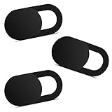
- Note: Not suitable for MacBooks released after 2023 or devices with a protruding front camera; Not applicable to full-screen or notch-style tempered glass screen protectors; Do not use on the rear camera of the phone.
- 💻 Why Do You Need a Webcam Cover Slide? — Safeguard your privacy by covering your webcam with our reliable webcam cover when not in use. Don't let anyone secretly watch you. Stay protected!
- ✅ Thin & Stylish — Enhance your laptop's functionality and aesthetics with our 0.027" ultra-thin webcam covers. Seamlessly close your laptop while adding a touch of sophistication.
- ✅ Fits Most Devices — Compatible with laptops, phones, tablets, desktops! Keep your privacy intact on Ap/ple, Mac/Book, iPh/one, iP/ad, H/P, L/novo, De/ll, Ac/er, As/us, Sa/msung devices.
- ✅ 365 Days Protection — Our upgraded 3.0 adhesive ensures a strong hold that won't damage your equipment. Experience reliable, long-term privacy protection day in and day out.
Does a vision-guided arm need a depth camera?
No. A depth camera is one practical way to obtain 3D information, not a universal requirement. An RGB-only system can estimate position when its geometry, camera setup, and task allow it, but an image classification or 2D location alone does not establish how far away an object is or whether a grasp is reachable.
The documented hardware examples use depth cameras: UFACTORY’s xArm vision and calibration examples name the Intel RealSense D435i, while PickNik’s MoveIt Pro UR5e hardware guide specifies a D415 or D435 for its example. Camera model alone does not establish compatibility. Check the robot and camera software support, mounting arrangement, cables, field of view, and the versions used by the integration.
Rank #4

- Anti-Slip Surface - Transform your laptop into a mobile workstation with the AboveTEK portable laptop lap desk. The anti-slip surface provides a strong grip for laptops up to 15.6 inches(Diagonal), while the double rubber strip on the bottom ensures a stable display or typing experience on your lap, couch, or bed.
- Retractable Mouse Pad - Retractable laptop mouse pad extends on both directions for the left/right handed with elevation along the edges for stopping mouse from falling off. The size of laptop tray is 14" X 9.7" and the size of mouse pad is 7.4" X 6.1".
- Effective Heat Shield - The effective heat shield made of sturdy and thick material protects your laptop from overheating. Prioritizes your comfort and safety, an ideal lap pad or board for working anywhere.
- EASY to Carry and Store - With an ergonomic and simplistic design, the lap desk is portable to store in a backpack. Only 15" in size, 2.2 lb of weight and with slim 0.6 inch thickness, it is ready to be easily carried around.
- Widely Applicable - The smooth platform accommodates laptops and tablets up to 15.6 inches(Diagonal), making it a versatile accessory and one of the best gifts for mom, dad, students and professionals. Perfect for use as a laptop bed tray or tablet holder anywhere at home, library, or park.
How does the arm move after it finds the object?
Once the system has a target pose, the motion layer must get the arm there while respecting its geometry and the task’s constraints. Three approaches represented in the documentation have different uses:
| Motion approach | How it works | Relevant trade-off |
|---|---|---|
| Planned trajectory with MoveIt | A motion planner produces a path to the target pose. | UFACTORY recommends MoveIt in its demo for singularity and collision-free execution. A planned path still depends on suitable models, targets, configuration, and the real setup. |
| Direct arm API commands | Application code sends commands through the robot’s API. | UFACTORY notes that its API route is less demanding of real-time network performance, but warns that it can fail near a singularity or self-collision. |
| Visual servoing | The system repeatedly measures pose error and sends motion commands to reduce it. | MoveIt Pro’s example uses Cartesian velocity commands with configured speed limits and completion thresholds. Its page warns that the example is being migrated and may not be fully functional. |
Visual servoing is useful when the system needs to adjust motion based on successive observations rather than rely only on a move planned from an initial estimate. It is not a substitute for calibration or sensible motion limits: errors in perception and frame relationships can still direct the arm incorrectly.
Recommended Free Tools
Best Value

- Spacious Design: Measuring 21.1" wide and 12" deep, our lap desk comfortably fits most laptops up to 15.6". Extra room for accessories ensures convenience.
- Enhanced Functionality: Packed with handy features, including a 5x9" precision tracking mouse pad and a built-in phone slot for seamless work or video calls. Plus, enjoy laptop support with the integrated device ledge.
- Cool Comfort: Enjoy a stable surface with our lap desk's dual bolster cushion, designed for comfort and airflow, keeping your lap cool during extended use.
- Durable Surface: Work with confidence on our lap desk's solid surface, featuring a blush pink color, ensuring optimal air circulation to prevent your laptop from overheating.
- On-the-Go Convenience: With an integrated handle and lightweight design (2.14 lbs), our lap desk is portable for travel or moving around the house, offering flexibility in any space.
What hardware can form a working example?
The published examples are integration references, not a universal shopping list. For example, PickNik’s MoveIt Pro UR5e hardware guide specifies a UR5e arm, Robotiq 2F-85 gripper, RGB-D camera, and wrist mount, with an optional scene camera. It also calls for secure robot mounting and sufficient operating space. That combination is a specialized example, not a default low-cost kit.
When comparing candidate systems, check the arm’s supported driver and software versions, the camera mount and field of view, the gripper, calibration tooling, and any network demands of the chosen control route. A camera’s product name by itself does not show that it will work with a particular arm or software stack.
How to build and validate a vision-guided pick
- Define the task and workspace. Choose the objects, grasp approach, pickup area, and destination. Confirm that the arm can physically reach the required poses.
- Choose the camera arrangement. Decide whether the task benefits more from a view attached to the tool or a view of the workspace from outside the arm. Account for occlusion and how the camera’s view changes during the task.
- Integrate and mount the hardware. Confirm the camera, arm driver, gripper, ROS 2 components, and mounts are supported by the software setup. Secure the arm and allow adequate operating space.
- Calibrate the geometry. Establish the camera-to-tool and robot-frame relationships required by the chosen setup, and save the resulting parameters where the application expects them.
- Validate perception before motion. Check that the target is detected consistently and that its estimated position makes sense relative to the camera and robot. Use a clear background and visually distinct target where practical.
- Configure the grasp and motion. Set the preparation pose, grasp orientation and depth, target, and movement speed for the actual object and workspace. Choose a planning or servoing route supported by the system.
- Test incrementally. Use simulation to validate the workflow before physical deployment, then verify calibration and motion on the real setup under controlled conditions. Simulation does not prove that the physical setup is safe or calibrated.
What commonly causes a failed pick?
- The object is detected but the arm reaches the wrong place: Check camera-to-robot calibration, saved parameters, and the frame used for the target coordinates.
- The target is hard to detect: Improve contrast or simplify the background, and check whether the object is visible from the selected camera placement.
- The gripper approaches at the wrong angle or depth: Revisit the grasp orientation and depth rather than assuming the object detector supplies a complete grasp pose.
- The arm cannot execute the commanded motion: Check whether the target is reachable and whether the route approaches a singularity or self-collision. UFACTORY specifically flags those risks for its API-driven alternative.
- The simulated behavior differs from the real setup: Recheck the physical mounting and calibration; a successful simulation is not proof that the real camera and arm share the expected geometry.
These checks address common integration problems, not a complete functional-safety specification. A deployed robot also needs safeguards appropriate to its hardware, workspace, and people nearby.
What published performance figures mean
A 2026 Journal of Robotics paper, “Manipulator Control Using CSRT Algorithm in Image-Based Visual Servoing Technique and ROS 2 Tools,” reports 80% total manipulation success across 40 grasping tasks on its particular system. The tested system used a 5-DOF arm, an eye-in-hand camera, sonar depth feedback, a CSRT tracker, ROS 2, and MoveIt Servo. The authors also report an average sonar depth error of 1.2 cm in a 5–30 cm working range. These are results for that study’s setup and evaluation, not a general success rate or accuracy guarantee for other arms, cameras, objects, or workspaces.
Free tools Windows power users keep installed
One-click scans. No signup required.
Quick Recap
Product prices and availability are accurate as of the date/time indicated and are subject to change. Any price and availability information displayed on Amazon at the time of purchase will apply.