What’s actually slowing this PC down?
Pick the symptom - the matching free tool is one click away.
You can build a camera bot around the camera-capable FireBeetle 2 ESP32-S3 AI board, using its DVP camera connector and the Arduino ESP32 CameraWebServer example for browser video. The FireBeetle documentation does not provide a complete, tested chassis, motor-driver and power circuit, so the drivetrain must be designed around your motors and driver. If you want camera and motor control on one robotics board, DFRobot’s Romeo ESP32-S3 is a separate, documented alternative.
Choose the correct FireBeetle ESP32-S3
Buy the camera-capable AI board, not the N4
Look for the FireBeetle 2 ESP32-S3 AI board (commonly identified with the N16R8/AI designation) and verify that the PCB has a CAM connector. The related FireBeetle ESP32-S3 N4 does not have a camera interface, so it cannot be used for this build without changing boards.
Check the sensor and board revision
DFRobot documents the CAM interface as compatible with OV2640 and OV7725 modules. A bundle may contain an OV2640 or OV3660, shipped at random. Confirm the sensor physically supplied and select the matching camera model in firmware; do not assume that every listing includes the same sensor.
Published board specifications
| Item | FireBeetle 2 ESP32-S3 AI specification |
|---|---|
| Processor | Dual-core Xtensa LX7, 240 MHz (vendor specification) |
| SRAM | 512 KB (vendor specification) |
| Flash | 16 MB (vendor specification) |
| PSRAM | 8 MB (vendor specification) |
| Wireless | 2.4 GHz Wi-Fi and Bluetooth 5 |
| Camera interface | DVP CAM connector |
These are published hardware figures, not measurements of video frame rate, latency, recognition accuracy or battery life.
Free tools Windows power users keep installed
One-click scans. No signup required.
#1 Best Overall

- 🔥【Dual Mode & High Performance】 The ESP32-S3 development board features integrated dual-core xtensa 32-bit LX7 microprocessor, clock speed up to 240 MHz, with 16MB Flash and 8 MB PSRAM. Perfect for Arduino IoT projects requiring stable wireless communication with ultra-low power consumption.
- 🔧【Easy Programming & Debugging】 Equipped with dual USB Type-C ports, this ESP32-S3 board supports both USB and UART modes for effortless programming, firmware flashing, and debugging.
- 🌐【Versatile Wireless Connectivity】 Built-in Wi-Fi (2.4GHz) and Bluetooth 5.0 (LE) dual-mode ensure seamless connectivity with a wide range of smart devices, making it ideal for IoT, smart homes projects.
- 🚀【Flexible Download Options】 Supports dual download methods — USB direct download or USB-to-serial download — offering flexibility and convenience for different development needs.Ideal for beginners and developers working with ESP32-S3.
- 🔋【Advanced Power-Saving Modes】 Designed for energy-efficient applications, with 3.3V SPI voltage, the ESP32-S3 board supports multiple low-power modes, allowing you to extend battery life based on different usage scenarios.
Decide on the robot architecture
| Approach | What it provides | What you must design |
|---|---|---|
| FireBeetle plus external driver | Flexible camera and Wi-Fi controller | Motor driver, motors, chassis, regulator, wiring, grounding and GPIO allocation |
| Romeo ESP32-S3 | Integrated camera and motor driver for a robotics build | Chassis, motors, battery and software configuration; it is not FireBeetle hardware |
Use the FireBeetle architecture when you already have a suitable driver or need a general-purpose ESP32-S3 controller. Choose Romeo when minimizing motor-control wiring is more important than using the FireBeetle board.
Bring up the FireBeetle camera
- Install the ESP32 board support package in Arduino IDE and connect the FireBeetle by USB.
- Open File → Examples → ESP32 → Camera → CameraWebServer.
- Select
CAMERA_MODEL_DFRobot_FireBeetle2_ESP32S3in the example. - Set the camera definition to match the sensor actually installed, such as OV2640 or OV7725 where applicable.
- Identify the physical board revision before handling camera power. DFRobot states: “Only the hardware version V1.0 requires the use of the AXP313A library.” On V1.0, add that library and use the documented camera-power enable call. On V1.1 and later, the camera example can be used directly with the FireBeetle model selected.
- Compile and upload, open the serial monitor at the baud rate shown by the example, and note the IP address after Wi-Fi connects.
- Open that address in a browser on the same network and confirm that the stream and camera controls load before attaching motors.
Earlier FireBeetle revisions use an AXP313A-managed camera supply. The wiki describes three independent power circuits on V1.2 and later, so do not apply a V1.0 power procedure indiscriminately to another revision.
Rank #2

- ✅【High-Performance ESP32-S3 Processor】Powered by the ESP32-S3 dual-core Xtensa LX7 processor with up to 240MHz clock speed, this development board features 16MB Flash and 8MB PSRAM. It provides powerful performance for IoT devices, embedded systems, AI applications and advanced DIY projects.
- ✅【Pre-Soldered GPIO Headers for Easy Use】The board comes with pre-soldered GPIO headers, eliminating the need for manual soldering. It can be directly connected to breadboards, sensors and expansion modules, making project setup faster and more convenient for makers and developers.
- ✅【WiFi & Bluetooth 5.0 Wireless Connectivity】Built-in 2.4GHz WiFi and Bluetooth 5.0 enable stable wireless communication for smart home, automation and IoT applications. The reserved IPEX antenna connector allows optional external antenna installation for different project requirements.
- ✅【Large Memory & Flexible Development】With 16MB Flash and 8MB PSRAM, this ESP32-S3 board provides more storage and memory resources for complex firmware, graphical interfaces, OTA updates and data-intensive applications.
- ✅【Arduino IDE, ESP-IDF & MicroPython Support】Compatible with Arduino IDE, ESP-IDF and MicroPython development environments. With dual USB-C interfaces and rich expansion options, it is suitable for robotics, sensors, automation and embedded system development.
Design the drivetrain around the actual motors
Select a driver by stall current and voltage
The FireBeetle sources do not certify a particular external motor driver or provide a complete FireBeetle camera-bot wiring diagram. Choose a driver whose motor-voltage range and continuous and stall-current ratings cover your motors. Keep motor power within the driver’s specification and reserve a regulated supply for the ESP32-S3 logic.
Plan grounds, power and GPIO before wiring
- Use a common signal reference between FireBeetle and the motor driver.
- Do not feed motor current through the board’s logic-power path.
- Provide regulation appropriate to the battery and the ESP32-S3 input requirements.
- Reserve GPIOs for the driver’s direction, enable or PWM signals and any encoders; check for conflicts with the camera interface and boot functions.
- Add physical mounting and strain relief so the camera cable cannot be pulled by the chassis.
Exact pin assignments depend on the selected driver and board revision. Follow those parts’ datasheets rather than copying an unverified pin map.
Rank #3

- ESP32-S3-Zero development board based on ESP32-S3FH4R2, equipped with 32-bit LX7 dual-core processor, up to 240MHz main frequency
- ESP32-S3 Mini board supports 2.4GHz Wi-Fi (802.11 b/g/n) and Bluetooth 5 (LE), built in 512KB of SRAM and 384KB ROM, onboard 4MB Flash memory and 2MB PSRAM
- Integrated with USB serial port full-speed controller, 34 × GPIO pins allows flexibly configuring pin functions, 4 × SPI, 2 × I2C, 3 × UART, 2 × I2S, 2 × ADC, etc.
- Supports flexible clock, module power supply independent setting, and other controls to realize low power consumption in different scenarios
- Castellated module and onboard ceramic antenna, allows soldering direct to carrier boards, suitable For SMD Applications
Choose 2WD or 4WD deliberately
A 2WD differential-drive chassis generally needs two independently controlled motor channels. A 4WD design may use four motors or pair motors mechanically/electrically, changing current demand and control complexity. Size the battery, regulator and driver for the worst-case stall load, not only the no-load running current.
How video and motor control fit together
The CameraWebServer example is a camera-streaming starting point. Add motor-control handlers only after the video path works. A practical control loop is:
Rank #4

- Please note!!! This product requires a 3.7V MX1.25 lithium battery for operation, which is not included. Please purchase it separately.
- High-Performance MCU: The board is equipped with the ESP32-S3R8 module, featuring a powerful Xtensa 32-bit LX7 dual-core processor that operates at up to 240MHz, ensuring efficient processing for various smart applications.
- Wireless Connectivity: With built-in support for 2.4GHz Wi-Fi (802.11 b/g/n) and Bluetooth 5 (LE), the ESP32-S3-AUDIO-Board offers robust wireless capabilities, facilitated by the onboard antenna for seamless communication and connectivity.
- Advanced Voice Interaction: The dual microphone array is designed with noise reduction and echo cancellation features, enabling accurate speech recognition and responsive near/far-field wake-up functionality, perfect for voice-activated applications.
- Dynamic Lighting Effects: Equipped with 7x programmable surround RGB LEDs, the board allows the creation of vibrant and colorful lighting effects, enhancing user interaction and visual appeal for projects.
- Serve a control page or API from the ESP32-S3 alongside the camera view.
- Translate forward, reverse, left, right and stop commands into the driver’s direction and PWM signals.
- Implement a command timeout that stops the motors if browser connectivity is lost.
- Keep camera capture and network handling responsive by avoiding long blocking motor routines.
- Test with the wheels lifted, then at low speed on the floor, with an accessible emergency power disconnect.
The reviewed FireBeetle documentation does not establish a particular frame rate, latency, tracking quality or autonomous-navigation performance. Measure those characteristics on your completed robot if they matter to your project.
Independent reader supportYour contribution helps us test, update, and keep practical guides available for everyone.When Romeo ESP32-S3 is the better fit
DFRobot’s Romeo ESP32-S3 combines an OV3660 camera with a four-channel 2.5A H-bridge motor driver. Its documented motor input range is 5–24 V, with PH/EN or PWM control modes. DFRobot’s camera-car practice uses the board with four TT motors with encoders: the board creates an access point, you connect to it, open 192.168.4.1, drive the car and view camera data in the browser.
Best Value
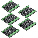
- Expands each GPIO pin on the ESP32-S3 into two pins, enabling connection to more sensors, displays, and modules to maximize pin utilization.
- Features a standard 44-pin GPIO interface, perfectly compatible with 44-pin development boards like the ESP32-S3 N8R2/N16R8—ensuring a tight fit, secure connection, and reliable signal transmission.
- This expansion board ensures stable circuit connections and reliable signal transmission, effectively preventing poor contact or intermittent failures in projects.
- It is ideal for complex systems such as multi-sensor configurations, as it keeps the workspace tidy while providing easy access to all I/O pins.
- Delivers a robust, organized pin expansion platform for intricate IoT projects, accelerating development and enhancing system stability—so you can focus on innovation.
This is an integrated Romeo design, not a FireBeetle shield or a validated FireBeetle drivetrain. Select it when the documented all-in-one robotics layout matches your motor and chassis requirements.
Troubleshoot common failures
No camera appears
- Recheck that the board is the AI camera variant and that a CAM connector is present.
- Inspect cable orientation and seating.
- Verify the camera model definition.
- Confirm the board revision and apply the V1.0 AXP313A power procedure only when appropriate.
The stream works but motors do not move
- Verify a separate motor supply and its voltage.
- Check the common ground and driver enable state.
- Confirm that the driver can deliver the motors’ startup and stall current.
- Check GPIO conflicts and PWM configuration.
The board resets when motors start
Motor transients are commonly a power-system problem. Separate motor and logic regulation, improve wiring and decoupling according to the driver and regulator documentation, and test with a current-limited supply before using a battery pack.
Quick Recap
Build checklist
- Camera-capable FireBeetle 2 ESP32-S3 AI board with verified SKU and CAM connector.
- Compatible camera sensor, with firmware selection matching the sensor in hand.
- Motor driver rated for the chosen motors’ voltage and stall current.
- Motors, 2WD or 4WD chassis and suitable mechanical mounts.
- Regulated logic supply, motor battery, common ground and safe power switch.
- Reserved GPIOs for driver control and optional encoders.
- CameraWebServer tested before drivetrain integration.
- Software stop timeout and a physical emergency disconnect.
Product prices and availability are accurate as of the date/time indicated and are subject to change. Any price and availability information displayed on Amazon at the time of purchase will apply.