Quick wins for a faster PC:
Scan for outdated or missing drivers - takes under a minuteDriver Scan →Repair Windows errors before they cause bigger problemsFix Now →Fix the driver behind crashes, sound loss and screen glitchesFind Drivers →Some links on this page are affiliate links: if you buy through them we may earn a commission, at no extra cost to you.
The Spectral Micro is a compact, open-source three-phase FOC motor controller for low-power robotic actuators. It combines a 14-bit magnetic encoder, inline current sensing, position/velocity/torque/impedance control, UART, and CAN in a board measuring about 39 × 39 mm and weighing roughly 8 g.
It is a strong option for gimbals, grippers, compact joints, robotic arms, and experimental legged robots. It is not a drop-in industrial servo: the product is documented as beta hardware, requires careful encoder-magnet alignment and calibration, and is limited to a published maximum phase current of 2.8 A and maximum power figure of 80 W.
What is the Spectral Micro BLDC Driver?
The Spectral Micro BLDC Driver—also called the Spectral Micro BLDC Controller—is a complete motor-control board from Source Robotics, a Croatia-based open-source robotics company. Source Robotics publicly released it in November 2024.
Unlike a basic six-step electronic speed controller, the Spectral Micro uses field-oriented control (FOC) to regulate a three-phase BLDC or PMSM-style motor. Its onboard magnetic encoder provides rotor-position feedback, while current sensing lets the firmware control torque more precisely.
#1 Best Overall

- Product Parameters: BLDC brushless control board wide voltage 6-60V, high power 400W, DC three-phase brushless hall controller, support for PLC 0-5V touch volume control, support for PWM control, amplitude 2.5-5V. This driver is only applicable to the electric angle of 120 degrees of DC brushless hall motor
- Note: Brushless motors also generally have five Hall wires or interfaces. Two of them are hall power supply line, three are hall signal line, to distinguish especially hall power supply line. Three Hall signal lines are generally labeled a b c, the driver board also has ha Hb Hc three ports and other similar characters, respectively, corresponding to connect
- Features: MA MB MC phase line output motor. 5V GND The mainboard comes with a 5V power supply. VCC GND Main power supply. SC speed pulse signal output. DIR Direction control Forward/reverse control interface. STOP Stop the control interface. BRAKE Brake control Indicates the brake control port. Speed control Input speed control signals. Ha Hb Hc +5V GND Hall signal power supply input interface. Generally, the motor with Hall has the corresponding 5 wires
- Note: This controller requires hall to function. If your motor doesn't have a hall then it won't work. The brushless motor application scenarios are very wide, such as electric vehicles, drones, fans, range hoods
- Package: The product comes with 2pcs of Brushless Motor Controller and wires
- BLDC motor: the motor being driven.
- FOC: the control method used to regulate phase current and motor torque.
- Encoder: the position sensor used for closed-loop commutation and servo control.
- Controller: the electronics and firmware that power the motor phases and interpret commands.
The board is aimed at compact robotic actuators, including gimbal motors, quadrupeds, robotic arms, and grippers. It is not designed as a high-power traction inverter, industrial servo drive, or spindle controller.
Source Robotics labels the product and its documentation as beta, with firmware and documentation still developing. That makes it particularly interesting for research, education, prototypes, and open-source robotics. Production or safety-critical use requires application-specific qualification.
Read the official Spectral Micro documentation.
Key specifications
| Specification | Published information |
|---|---|
| Motor type | Three-phase BLDC/PMSM-style motor |
| Control | Field-oriented control |
| Normal product-page voltage range | 12–28 V |
| Documented absolute voltage range | 10–29 V |
| Maximum phase current | 2.8 A |
| Maximum power figure | Approximately 80 W |
| Control-loop frequency | 5 kHz |
| PWM switching frequency | 25 kHz |
| Maximum electrical frequency | 460 Hz |
| Encoder | 14-bit magnetic encoder |
| Interfaces | CAN and UART |
| MCU | STM32F103C |
| Dimensions | Approximately 39 × 39 mm |
| Mass | Approximately 8 g |
| Mounting | NEMA-17-compatible hole spacing |
| Documented operating temperature | −20 °C to 130 °C |
| Default UART | 256,000 baud, 3.3 V logic |
| Default CAN | 1 Mbit/s, node ID 0 |
These figures come from the official specifications and product page.
Recommended Free Tools
How to interpret the limits
The product page presents 12–28 V as the operating range, while the datasheet lists 10–29 V as absolute minimum and maximum ratings. Treat 10–29 V as an electrical limit, not a recommended everyday supply range. A nominal 12–24 V, current-limited supply is the sensible starting point unless the documentation for the specific hardware and firmware revision says otherwise.
The 2.8 A value is a ceiling, not a guarantee of unlimited continuous current. Continuous output depends on cooling, duty cycle, motor characteristics, supply behavior, and board temperature. Similarly, the 80 W figure is published product or system power—not guaranteed mechanical shaft output.
What hardware do you need?
A bare controller is not a complete actuator. At minimum, plan for:
- Spectral Micro controller.
- Compatible three-phase BLDC motor.
- Diametrically magnetized encoder magnet.
- Nominal 12–24 V power supply.
- Motor-phase wiring and power wiring.
- A programming or communications method.
- Computer or single-board computer.
- Secure mounting hardware or a motor bracket.
The starter kit adds a CANvas USB-to-CAN adapter, USB-to-serial adapter, ST-Link/JTAG programming hardware, cables, a diametrical magnet, and a 100K NTC thermistor. It still requires a motor, 12–24 V supply, USB-C cable, and computer or SBC.
Do these 3 things before closing this tab:
1Scan for outdated or missing drivers - takes under a minute2Repair Windows errors before they cause bigger problems3Fix the driver behind crashes, sound loss and screen glitchesAs observed on August 18, 2026, Source Robotics listed the bare controller at €85.68 and the starter kit at €154.70. The pages showed 19 controllers in stock and five starter kits remaining at that time. Prices, stock, VAT treatment, shipping, import taxes, duties, and brokerage charges can change.
Motor and encoder compatibility
The Spectral Micro is best matched with gimbal-style motors and compact robotic joints whose current and speed requirements fit the board. Do not assume that every three-phase motor will work well.
Check the motor’s:
- Nominal voltage and phase-current requirement.
- Pole-pair count and required speed.
- Winding resistance and inductance.
- Torque, inertia, and intended duty cycle.
- Thermal behavior under stall or continuous load.
- Mechanical arrangement for mounting the board and magnet.
- Compatibility with a gearbox, if one is used.
Consult Source Robotics’ tested-motors documentation rather than relying only on a motor’s voltage rating.
Rank #2
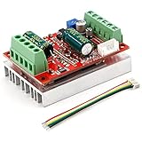
- 3-Phase BLDC Motor Compatibility & Core Specs:This controller operates exclusively with 120° electric angle 3-phase brushless DC motors equipped with Hall sensors. It supports a 6-60V DC input, delivers 200-300W rated power (350W peak) with 16A continuous (20A peak) output, and enables PLC-compatible 0-5V analog or PWM (2.5-5V amplitude, 50Hz-20kHz frequency) speed control—ideal for DIY robotics, small electric tools, brushless pumps, cooling fans, and industrial automation setups.
- Multi-Mode Speed & Direction Control:Adjust speed via the on-board potentiometer, external 0-5V analog input, external potentiometer, or PWM signal. It integrates forward/reverse, stop, and brake functions: note that forward/reverse and brake operations use hard commutation, so reduce speed throttle to below 50% before activation to protect power components from damage.
- Practical Design & Safety Guidelines:Features terminal block interfaces for easy wiring and a standard heat sink for stable heat dissipation. Built-in overcurrent protection safeguards the motor output; the main power circuit lacks a fuse, so external fusing is recommended. Reversing DC power polarity will permanently damage on-board chips, even under brief high-current conditions.
- Safe Initial Testing & Wiring Troubleshooting:For first use, test with low voltage (7-12V) and low current (1-3A) to validate wiring. If the motor jitters, fails to start, or runs in one direction only, adjust the sequence of the 3 motor phase wires (6 possible combinations, only one correct) to resolve mismatches—avoid high-current/high-voltage testing during troubleshooting to prevent module damage.
- Wide Application Scenarios:Suited for a range of projects: DIY robotics and model vehicles, small electric tools (mini drills, grinders), industrial automation (conveyors, lab mixers), fluid equipment (brushless water pumps, fans), and PLC-controlled systems, offering reliable speed regulation for brushless motor setups.
Encoder magnet alignment is critical
The encoder is located at the center of the PCB. The motor needs a suitable diametrically magnetized magnet aligned with the encoder, with approximately 1 mm of spacing according to the getting-started documentation.
A wrong magnet, excessive air gap, off-center installation, axial magnetization, shaft wobble, or poor concentricity can cause failed calibration, noisy feedback, vibration, or runaway motion even when the phase wiring is correct. Mount the magnet rigidly and verify that it rotates concentrically with the motor shaft.
Wiring and first power-up
Important: Reversing DC+ and DC− can destroy the board. The UART interface is 3.3 V only; applying 5 V logic can damage the controller. The official documentation also warns that incorrect CAN or power-cable orientation in a daisy chain can destroy a motor controller.
| Connection | Purpose | Important check |
|---|---|---|
| DC+ / DC− | Motor-controller power | Verify polarity before applying power |
| U / V / W | Three motor phases | Use secure, insulated connections |
| UART | Setup, information, debugging, and single-axis control | 3.3 V logic; default 256,000 baud |
| CAN | Multi-axis networking and control | Check cable orientation, bus speed, IDs, and termination |
| JTAG | Firmware flashing and low-level programming | Use the documented adapter and stable power |
| Thermistor | Motor-temperature monitoring | Place the NTC between motor coils where practical |
Use this first-power-up sequence:
- Mount the board securely to the motor or bracket.
- Install and center the diametrical magnet, targeting approximately 1 mm spacing.
- Connect U, V, and W.
- Connect DC+ and DC− with polarity checked.
- Connect UART, CAN, or JTAG as appropriate.
- Add the thermistor if winding-temperature monitoring is needed.
- Inspect connector orientation and exposed conductors.
- Apply current-limited 12–24 V power.
- Connect to the board and use the documented information command, such as
#Info, to inspect firmware information. - Calibrate before commanding motion.
- Begin with low current, velocity, and position limits while the motor is mechanically unloaded.
See the official getting-started guide for the current wiring diagrams.
Calibration and tuning
Calibration is mandatory for a reliable closed-loop actuator. A newly powered board should not be assumed to know the motor’s pole pairs, electrical characteristics, or encoder alignment. The published defaults include calibration disabled, pole pairs set to zero, and resistance and inductance set to zero.
PC Slower Than It Used to Be?
A free scan shows the junk files, broken settings and background clutter dragging Windows down - then fixes them in one click.Free scan · Windows 10 & 11Outdated Drivers Are Slowing You Down
One free scan finds every outdated or missing driver and matches the right update for your exact hardware.Free scan · exact hardware matchDepending on the firmware workflow, calibration involves motor pole-pair count, phase resistance, inductance where required, encoder direction and alignment, current sensing, motion limits, and temperature-sensor configuration.
- Secure the motor and remove the mechanical load.
- Confirm that the magnet is centered and the encoder readings change smoothly when the shaft is turned.
- Enter the correct pole-pair count.
- Run the official calibration procedure.
- Check encoder direction and phase relationships.
- Set conservative current and velocity limits.
- Command small movements.
- Watch for vibration, noise, unexpected rotation, or heating.
- Only then tune PID parameters.
Incorrect encoder direction or command sign can produce runaway motion. Keep an immediate power-disconnect method available, and do not begin testing with a gearbox, arm, gripper, or human-interacting mechanism attached.
UART, CAN, Python, Arduino, ROS 2, and SimpleFOC
UART
UART is useful for initial configuration, firmware inspection, calibration, debugging, and single-board experiments. The documented default is 256,000 baud with 3.3 V logic. Use the current UART documentation rather than assuming commands from an old firmware version remain unchanged.
CAN
CAN is the natural choice for a multi-axis robot. Multiple drivers can share a bus through daisy chaining. The documented default is 1 Mbit/s and the default node ID is 0, but every controller in a real network needs a unique node ID and matching bus settings.
Free tools Windows power users keep installed
One-click scans. No signup required.
The first and last nodes should provide bus termination. The board’s termination switch can enable termination. Common problems include missing or excessive termination, duplicate IDs, mismatched baud rates, reversed cable orientation, poor grounding, excessive cable length, and a bus that is electrically active but receiving no valid application-level commands.
Rank #3

- MA MB MC phase line output connection motor
- Ha Hb Hc +5V GND Hall signal Power input, generally with Hall's motor has five corresponding lines Full patch process Stable performance with positive/reverse function
- positive and negative reversing control interface (also can be connected to the external switch) VR speed control signal input (onboard with potentiometer speed control can also be connected to 0-5V analog simulation PWM duty cycle to support dual signal input speed regulation)
- VCC GND motor main power supply (external DC power supply) SC speed pulse signal output
- 5V GND motherboard comes with 5V power supply (current does not exceed 30MA)
Source Robotics’ CANvas USB-to-CAN adapter is described as an open-source SLCAN-based adapter with split termination, common-mode-choke filtering, and TVS protection.
Python, Arduino, ROS 2, and SimpleFOC
Source Robotics advertises Python, Arduino, ROS 2, GUI, and SimpleFOC compatibility. These are different integration paths rather than interchangeable operating modes:
- Python: convenient for computer-based experiments and test automation.
- Arduino: useful for embedded development and board-level experimentation.
- ROS 2: suitable when a robot’s high-level control stack already uses ROS 2; verify the current package and tested distribution before choosing a specific ROS 2 release.
- SimpleFOC: attractive for developers who want a familiar open-source motor-control framework, but board-specific configuration and encoder integration may still be required.
- Preloaded Spectral firmware: the shortest route to a working actuator.
- Custom firmware: offers control over behavior but requires JTAG hardware, firmware knowledge, and a recovery plan.
Performance expectations
Electrical frequency and motor speed
The 460 Hz maximum electrical frequency is not a universal motor RPM limit. Mechanical speed depends on pole-pair count:
Electrical frequency = mechanical revolutions per second × pole-pair count
Therefore, the approximate mechanical-frequency ceiling implied by the published limit is:
Mechanical revolutions per second ≈ 460 ÷ pole-pair count
A high-pole-count motor reaches the electrical-frequency limit at a lower mechanical RPM than a low-pole-count motor. This is an engineering inference from the specification, not a manufacturer-published maximum RPM guarantee.
What’s actually slowing this PC down?
Pick the symptom - the matching free tool is one click away.
Torque, power, and cooling
Torque depends on the motor, phase current, magnetic design, gearing, speed, and control tuning. The controller’s 2.8 A current ceiling does not translate directly into one universal torque value. A gearbox can increase output torque, but it also adds inertia, friction, reflected load, and thermal demand.
Continuous stall or high-torque operation is especially demanding. A small PCB may overheat even when average mechanical power seems modest. The optional 100K NTC thermistor is useful for monitoring motor-winding temperature; Source Robotics recommends positioning it between the motor coils. Board protection for overcurrent, undervoltage, overvoltage, and temperature is helpful, but it does not replace thermal design or current limiting.
Independent reader supportYour contribution helps us test, update, and keep practical guides available for everyone.Common problems and fixes
| Symptom | Likely causes | First checks |
|---|---|---|
| Board does not power up | Reversed polarity, insufficient supply, damaged connector, undervoltage | Verify DC+ and DC−, measure voltage at the board, use current limiting |
| Board fails immediately | Reversed power or incorrect daisy-chain cable orientation | Compare every connector with the official wiring diagram |
| Encoder is frozen or inaccurate | Wrong magnet, poor centering, excessive air gap, damaged sensor | Use a diametrical magnet and check approximately 1 mm spacing |
| Calibration fails | Wrong pole pairs, phase order, encoder alignment, mechanical obstruction | Check motor data, phase wiring, magnet alignment, and unloaded rotation |
| Motor vibrates or growls | Bad calibration, wrong encoder direction, excessive PID gains, wrong pole pairs | Recalibrate, lower gains, verify sensor direction |
| Motor runs away | Incorrect feedback polarity, command sign, or invalid calibration | Cut power immediately and check encoder direction and control sign |
| Motor overheats | Excessive current, stall, poor cooling, aggressive tuning, overload | Reduce current, test unloaded, and monitor motor temperature |
| UART fails | Wrong baud, 5 V logic, swapped TX/RX, unsuitable adapter | Use 3.3 V UART and the documented 256,000-baud default |
| CAN nodes do not communicate | Wrong baud, duplicate IDs, termination fault, reversed cable | Check 1 Mbit/s, unique IDs, termination, and cable orientation |
| CAN is intermittent | Poor wiring, missing reference, noise, excessive length, bad termination | Test one node, inspect topology, and verify termination |
| Firmware update fails | Incorrect JTAG wiring, unstable power, interrupted flashing, wrong target | Use the documented programmer and do not interrupt power |
| High-speed motion is unstable | Electrical-frequency limit, encoder error, poor tuning, unsuitable motor | Calculate electrical frequency and increase speed gradually |
The official documentation provides separate pages for flashing, calibration, PID tuning, UART, CAN, tested motors, and troubleshooting.
Rank #4

- Working for BLDC Motor ,Working voltage DC10-30V,Max Working Power 300W
- Function:Speed regulation/inching/timing/limit/output control/temperature limiting protection/CW/CCW/power-off memory
- 23 types Working Mode ,Support Modbus communication;The module has built-in multiple fixed operation modes, and users can quickly select the appropriate motion trajectory to meet different application scenarios
- LCD Display: The LCD screen can clearly display the speed/delay/cycle time, control the motor with high precision, and the controller parameters support the memory function that will not be lost
- Application areas: Unmanned aerial vehicle motors, water pumps, oil pumps, air pumps, electric tools, thrusters, and other general industrial control applications, cannot be used in special industries such as medical, firefighting
Is the Spectral Micro suitable for production?
For prototypes, education, research, and open-source robots, the Spectral Micro’s size, low mass, integrated sensing, CAN support, and accessible firmware are compelling. It can reduce the electronics work needed to build a custom actuator.
For production, qualification is the key issue. The beta status, evolving firmware and documentation, limited current, external encoder-magnet installation, and lack of an indicated industrial safety-certification package in the reviewed sources mean that a project team must validate reliability, thermal behavior, fault handling, vibration resistance, firmware versioning, and serviceability itself.
Do not infer collaborative-robot safety from current sensing or gripper applications. Safety requires a complete system-level risk assessment, mechanical limits, emergency-stop behavior, fault detection, and appropriate certification for the intended machine.
Alternatives
STEPFOC
STEPFOC is a related Source Robotics controller optimized for NEMA-17 stepper motors. The company says it shares much of the Spectral platform, but it is not a direct substitute for a conventional BLDC controller. Choose it when the project starts with a stepper and needs closed-loop FOC control.
Custom SimpleFOC hardware
A separate MCU, gate driver, current-sense circuit, encoder, MOSFET stage, and protection design offers maximum flexibility and educational value. It also makes the designer responsible for PCB layout, firmware, thermal behavior, fault protection, and debugging. Spectral Micro is preferable when those functions should arrive on one small board.
Integrated commercial servo actuators
An integrated servo normally combines a motor, encoder, gearbox, controller, and housing. It can reduce mechanical and software integration work and may offer better support and known actuator specifications. The trade-offs are higher cost, less openness, and less flexibility for unusual motors or gearboxes.
Higher-power FOC controllers
Industrial and robotics-oriented controllers may provide higher current, more mature diagnostics, stronger thermal design, and broader compliance documentation. They are usually larger, more expensive, or more proprietary. Compare current and voltage range, encoder support, CAN protocol, firmware openness, thermal performance, safety functions, documentation, and production support rather than price alone.
Buying options and total cost
Prices below were observed on August 18, 2026 and are not guarantees:
| Item | Observed price | Use |
|---|---|---|
| Spectral Micro controller | €85.68 | Bare controller for buyers who already have compatible hardware |
| Starter kit | €154.70 | Controller plus CAN, UART, JTAG, cables, magnet, and thermistor |
| CANvas adapter | €47.60 | PC-to-CAN and multi-axis setup |
| JTAG adapter | €23.80 | Firmware flashing |
| USB-to-serial adapter | €29.75 | UART setup and configuration |
| 100K NTC thermistor | €3.57 | Motor-winding temperature monitoring |
| Diametrical magnet | From €4.76 | Encoder sensing |
| Power cable | From €5.36 | Power connection |
| CAN or UART cable | €5.95 each | Communications and daisy chaining |
A functioning actuator also needs the motor, power supply, mechanical bracket, wiring, and possibly a gearbox. Buying only the €85.68 board is a poor fit if you do not already own the remaining development hardware.
The Tool Desk
Outbyte PC Repair FREERepair Windows errors before they cause bigger problemsFix Now →Outbyte Driver Updater FREEFix the driver behind crashes, sound loss and screen glitchesFind Drivers →Verdict
The Spectral Micro is a promising low-power FOC platform for builders who want a small, open-source controller for a compact robotic actuator. Choose it when your motor fits the 12–24 V development range, stays comfortably below the 2.8 A phase-current ceiling, can accept a precisely aligned diametrical magnet, and your project can tolerate beta firmware.
Reconsider it for high-power motors, industrially certified equipment, severe environments, safety-critical systems, or applications that need a turnkey enclosed servo. Its strongest advantage is integrated capability in an unusually small board; its decisive drawbacks are limited power, careful setup requirements, thermal constraints, and ongoing product maturity.
Quick Recap
Product prices and availability are accurate as of the date/time indicated and are subject to change. Any price and availability information displayed on Amazon at the time of purchase will apply.

