The Tool Desk
Outbyte PC Repair FREEClear out junk files and repair common Windows errorsFree Scan →Outbyte Driver Updater FREEFix the driver behind crashes, sound loss and screen glitchesFind Drivers →Some links on this page are affiliate links: if you buy through them we may earn a commission, at no extra cost to you.
Project #15: Environment is an ESP32-based environmental monitor and data logger, not simply a GPS project. The SparkFun GP-20U7 supplies location, GPS time, speed and—when a valid fix is available—navigation data. The BME280 and CCS811 provide the environmental readings, while an RTC, microSD card and Sharp Memory Display turn those measurements into a portable logging system.
The original Hackster project remains useful as an educational integration reference, but it is marked as a work in progress and its underlying u-blox MAX-7Q receiver is now an older, end-of-life component. Reproduce it for learning or historical fidelity; for a new long-term design, use a current GNSS receiver instead.
What the original project does
The project combines an ESP32 with environmental sensors, GPS, local storage and a display. Its intended data set includes:
Free tools Windows power users keep installed
One-click scans. No signup required.
| Data or function | Component |
|---|---|
| Latitude and longitude | SparkFun GP-20U7 GPS receiver |
| GPS time, speed and GPS altitude | GP-20U7, when valid navigation data is available |
| Temperature, humidity and pressure | BME280 |
| Estimated altitude from pressure | BME280 |
| eCO₂ and TVOC estimates | CCS811 |
| Battery-backed timekeeping | PCF8523 RTC |
| Persistent logging | microSD card |
| Human-readable output | Adafruit Sharp Memory Display |
| Device identification | EEPROM-stored identifier |
That combination is useful for geospatial environmental logging: a person or vehicle can collect readings along a route, associate them with coordinates, identify the collecting device and store the results for later mapping or comparison.
#1 Best Overall

- The SparkFun GPS-RTK Dead Reckoning Kit provides you with what you need to start with GPS Real Time Kinematics and the u-blox ZED-F9R.
- Includes: 1x SparkFun GPS-RTK Dead Reckoning Breakout - ZED-F9R, SMA (Qwiic) 1x GNSS Multi-Band Magnetic Mount Antenna - 5m (SMA) 1x Reversible USB A to C Cable - 0.8m.
- Features: 2x Qwiic Connectors, Integrated SMA connector for use with antenna of your choice, Concurrent reception of GPS, GLONASS, Galileo and BeiDou, 184-Channel GNSS Receiver, Receives both L1C/A and L2C bands.
- This breakout maximizes position accuracy in dense cities or covered areas compared to other GPS modules. Even under poor signal conditions, continuous positioning is provided in urban environments and available during complete signal loss (e.g., short tunnels and parking garages). The ZED-F9R is the ultimate solution for autonomous robotic applications that require accurate positioning under challenging conditions.
- Also included with this kit is a GNSS multiband antenna and a reversible USB-A to C cable. The antenna features a magnetic base receiving the classic L1 and L2 GPS bands. Meanwhile, the included cables will make sure hooking up each part in the kit is easy!
The GP-20U7 is therefore context, not the environmental instrument. It tells the ESP32 where and, potentially, when a reading was taken. The BME280 and CCS811 supply the environmental values.
The project page and linked source files are available on Hackster.io.
Original hardware
The documented bill of materials includes:
- SparkFun Thing Plus ESP32 WROOM
- Adafruit Sharp Memory Display
- SparkFun Environmental Combo Breakout with CCS811 and BME280
- Adafruit Adalogger FeatherWing with RTC and SD storage
- SparkFun GP-20U7 GPS Receiver
- CR1220 battery, 32 GB microSD card, slide switch, Qwiic cable, green LED, resistors, jumper wires, breadboard and USB cable
The listed parts describe the original build, not a universal recipe. ESP32 boards and peripheral revisions can use different pins, voltage arrangements and bus connections.
System architecture
GP-20U7  ── UART ──> ESP32
BME280   ── I²C ───> ESP32
CCS811   ── I²C ───> ESP32
RTC      ── I²C ───> ESP32
Display  ── SPI ───> ESP32
microSD  ── SPI ───> ESP32
The BME280, CCS811 and RTC share the I²C bus when their addresses do not conflict. The display and SD card can share SPI clock and data lines, but each device needs its own correctly configured chip-select signal. SD-card writes and display updates must also use the pin assignments expected by the particular board and firmware revision.
How the GP-20U7 connects
The receiver communicates with the ESP32 through a hardware UART and normally emits NMEA sentences at 9600 baud. The documented project code creates UART 2 and assigns GPIO 4 as the GPS receive pin:
Rank #2
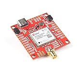
- Concurrent reception of GPS, GLONASS, Galileo and BeiDou. Receives both L1C/A and L2C bands, Time to First Fix: 25s (cold), 2s (hot)
- Voltage: 5V or 3.3V but all logic is 3.3V. Current: 68mA - 130mA (varies with constellations and tracking state). Weight: 6.8g. Dimensions: 43.5mm x 43.2mm (1.71in x 1.7in). 2x Qwiic Connectors
- This product is compatible with u-blox PointPerfect. Take your precision to the next level with the PointPerfect GNSS augmentation service.
- Max Navigation Rate: PVT (basic location over UBX binary protocol) - 25Hz. RTK - 20Hz. Raw - 25Hz
- Horizontal Position Accuracy: 2.5m without RTK. 0.010m with RTK. Max Altitude: 50km (31 miles). Max Velocity: 500m/s (1118mph)
HardwareSerial tGPS(2);
#define gpsRXPIN 4
tGPS.begin(9600, SERIAL_8N1, gpsRXPIN, gpsTXPIN);
In the physical connection:
- GPS TX connects to the ESP32 RX pin.
- GPS RX connects to the ESP32 TX pin only when the ESP32 must send configuration commands.
- GPS ground connects to ESP32 ground.
- GPS power must match the requirements of the exact receiver board.
The available project excerpt exposes the receive-pin assignment but does not show the complete transmit-pin declaration. Do not assume the missing TX pin. Confirm it in the exact source revision being used. Related project revisions also show different GPS assignments, including GPIO 14, so the published pin map is revision-specific rather than universal.
Also distinguish a bare GP-20U7 module from a carrier board. A bare module may require soldering and careful verification of supply voltage, logic levels, antenna connections and pin order. An integrated breakout may add regulation, headers, an antenna connector or indicator LEDs. SparkFun discusses this distinction in its GP-20U7 community guidance.
Test the GPS before adding the other peripherals
Start with power, ground and a UART pass-through. This isolates wiring and reception problems from SD, display and sensor problems:
#include <Arduino.h>

HardwareSerial GPSUART(2);

void setup() {
  Serial.begin(115200);
  GPSUART.begin(9600, SERIAL_8N1, 4, 5);
}

void loop() {
  while (GPSUART.available()) {
    Serial.write(GPSUART.read());
  }
}
The GPIO 4 and GPIO 5 values are only an example. Replace them with the pins actually wired to the selected ESP32 board. SparkFun’s GPS UART guide demonstrates the same basic approach.
At 115200 baud on the USB serial monitor, a working receiver should produce raw NMEA sentences such as GGA or RMC. Blank output usually indicates a power, ground, TX/RX, UART-pin or baud-rate problem. Check whether another peripheral already occupies the selected GPIOs.
Rank #3

- GT-U7 main module GPS module using the original UBLOX 7th generation chip, Software is compatible with NEO-6M. GT-U7 module, with high sensitivity, low power consumption, miniaturization, its extremely high tracking sensitivity greatly expanded its positioning of the coverage
- GPS baud needs to be set to 9600 instead of 4800; PPS pin is not needed unless using the GPS to drive a hardware high precision clock
- With a USB interface, you can directly use the phone data cable on the computer point of view positioning effect
- USB directly connected to the computer, That is, with the host computer-owned serial port function, no need for external serial module, send IPX interface active antenna
- Note: Please use the GT-U7 GPS module in an open place, the LED will flash after the satellite signal is found. Bad weather and indoor use will affect the accuracy of positioning
Parsing NMEA with TinyGPSPlus
The project uses the Arduino-compatible TinyGPSPlus library. Its include name is:
What’s actually slowing this PC down?
Pick the symptom - the matching free tool is one click away.
#include <TinyGPS++.h>

TinyGPSPlus gps;
A minimal parser loop looks like this:
void loop() {
  while (GPSUART.available() > 0) {
    if (gps.encode(GPSUART.read())) {
      if (gps.location.isValid()) {
        Serial.print("Latitude: ");
        Serial.println(gps.location.lat(), 6);
        Serial.print("Longitude: ");
        Serial.println(gps.location.lng(), 6);
      }
    }
  }
}
The parser receives bytes one at a time. Once a complete valid NMEA sentence has been decoded, the program can update its display or prepare a log record. The original project follows the same pattern:
while (tGPS.available() > 0) {
  if (gps.encode(tGPS.read())) {
    displayInfo();
  }
}
A valid serial stream is not the same as a valid position. A powered receiver may continuously output NMEA data while still searching for satellites. Check gps.location.isValid() separately from gps.charsProcessed(), and record the age of the last valid fix. The project’s five-second character-count diagnostic can reveal that no serial data is arriving, but five seconds is not a meaningful universal limit for acquiring a position.
Combining GPS and environmental data
A useful log record should make the source and quality of every field clear. For example, a record might contain:
- Device ID
- UTC timestamp and timestamp source
- Latitude and longitude, or an explicit “no fix” state
- GPS fix age and, where available, satellite or quality information
- GPS altitude, clearly labeled
- BME280 temperature, humidity and pressure
- BME280 pressure-derived altitude, clearly labeled
- CCS811 eCO₂ and TVOC estimates
Do not substitute invalid coordinates for missing data. Continue collecting environmental readings when GPS is unavailable, then mark the position as unavailable or attach the last-fix age. Likewise, define a clock policy: GPS time can discipline the RTC after a valid fix, while the RTC can provide continuity indoors or under obstructed skies. Store whether each timestamp came from GPS or the RTC, and keep UTC separate from local display time.
Do these 3 things before closing this tab:
1Scan for outdated or missing drivers - takes under a minute2Clear out junk files and repair common Windows errors3Fix the driver behind crashes, sound loss and screen glitchesRank #4
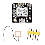
- GT-U7 main module GPS module using the original 7th generation chip, Software is compatible with NEO -6M
- GT-U7 module, with high sensitivity, low power consumption, miniaturization, its extremely high tracking sensitivity greatly expanded its positioning of the coverage. such as narrow urban sky, dense jungle environment, GT-U7 can be high-precision positioning
- GT-U7 GPS Module with a USB interface, you can directly use the phone data cable on the computer point of view positioning effect. USB directly connected to the computer, That is, with the host computer-owned serial port function, no need for external serial module, IPX interface active antenna included in the package!
- Operating voltage: 3.6V-5V (or direct usb power supply), Operating baud rate: 9600 (can be modified). Application: Vehicle-mounted, Handheld devices such as PDAs, Vehicle monitoring, Mobile phones, camcorders and other mobile positioning systems
- If you have any questions about using our products, such as needing technical documentation for a product .Please cilck''Geekstory'' to em-ail us. And you can also view the documentation(user manual) at the bottom of the details page
Important measurement qualifications
GPS altitude and BME280 pressure-derived altitude are not interchangeable. They use different measurement methods and reference assumptions, so both should be named explicitly in the log.
The CCS811 reports eCO₂ and TVOC estimates, not laboratory-grade direct CO₂ and air-quality measurements. Warm-up, calibration, environmental conditions and placement affect the results. The BME280 is practical for embedded monitoring, but its altitude estimate depends strongly on the reference pressure used.
This project should be described as a practical sensor logger, not a certified meteorological or air-quality instrument. Antenna placement, satellite geometry, obstructions and receiver conditions also determine GPS performance; no fixed accuracy figure should be promised without application-specific testing.
Common failures
No serial output
- Confirm GPS power and common ground.
- Cross the signals: GPS TX to ESP32 RX.
- Verify the UART instance and GPIO numbers.
- Use 9600 baud and 8-N-1 framing unless the receiver has been configured differently.
- Check for GPIO conflicts with the display, SD card or another peripheral.
- Verify that the exact board has the required antenna connection and voltage arrangement.
Serial data but no position
Test outdoors with a clear view of the sky, keep the receiver stationary and allow more time for a cold start. Print raw NMEA data, inspect gps.charsProcessed() and gps.location.isValid() independently, and log the time since the last valid fix.
SD-card errors
Check chip-select and SPI assignments, card formatting, power stability and write timing. Test the SD card independently before integrating it with the display and sensors. Avoid removing the card during a write and do not assume that a pin map from another ESP32 board applies to yours.
Best Value

- g28u7fttl gps comes with 3 cables to connect with breadboard, usb to ttl module, pc etc.
- g28u7fttl gps module built-in LNA signal amplifier, and flash to save configuration.
- Red LED means power supplied, and the green indicates gps fixed.
- 25x25x4mm high-sensitivity ceramic antenna on the back.
- Driver is required for using with windows.
RTC and GPS disagree
Choose an authority and document it. A sensible policy is to update the RTC from GPS after a valid fix, use the RTC during GPS outages and record the timestamp source in every log.
Should you still use the GP-20U7?
The GP-20U7 makes sense when you already own one, need to reproduce the 2020 project, or want to study a straightforward UART-and-NMEA implementation. It is less suitable for a new deployment where long-term supply, current documentation and supported hardware matter.
The receiver is based on the older u-blox MAX-7Q family. u-blox identifies the MAX-7 series as legacy and directs new designs toward newer MAX-M10 products. See the MAX-7 product-status page and its datasheet.
Crashes, No Sound, or Screen Glitches?
Random freezes, missing sound and display glitches usually trace back to one bad driver. Find and replace yours safely.Free scan · under a minuteWindows Errors? Fix Them Before They Spread
Repair common Windows errors and clear accumulated junk for a smoother, more stable PC - no reinstall needed.Free scan · no reinstallFor a modern build, select a current GNSS breakout with verified supply and logic levels, antenna requirements, UART defaults and library support. An integrated board is generally easier for prototyping; a bare module can be smaller and more flexible but demands more electrical verification.
Verdict
Project #15 is best understood as an ESP32 field-data platform whose GPS receiver adds geolocation and time context to environmental measurements. Its architecture is instructive: isolate and test the UART, parse NMEA incrementally, distinguish data reception from a valid fix, and preserve sensor and timestamp quality in the log.
Use the original GP-20U7 for an educational or historical reproduction. For a new product or long-lived outdoor deployment, retain the project’s system design but replace the end-of-life GPS hardware with a currently supported GNSS module and revalidate the wiring, firmware and data-quality assumptions.
Quick Recap
Product prices and availability are accurate as of the date/time indicated and are subject to change. Any price and availability information displayed on Amazon at the time of purchase will apply.

