What’s actually slowing this PC down?
Pick the symptom - the matching free tool is one click away.
Some links on this page are affiliate links: if you buy through them we may earn a commission, at no extra cost to you.
On the PIC18F45K50, FOSC selects the primary oscillator mode; it does not, by itself, select the internal oscillator’s operating frequency. FOSC = INTOSCIO selects the internal oscillator and assigns the oscillator-related pin for I/O. Set the internal high-frequency oscillator rate separately with the documented OSCCON controls, including IRCF. PLL selection and enable controls are another device-specific layer.
First, confirm the exact PIC
This explanation is for the PIC18F45K50. Configuration names and encodings are not portable across PIC devices, even when their names look similar. If your project uses another part, use that device’s data sheet and compiler header instead. The original question arose in a PIC18F45K50 forum discussion, but the device data sheet is the authority for its settings.
For the exact part, consult Microchip’s PIC18(L)F2X/45K50 Data Sheet, DS30000684, especially its oscillator-mode, configuration-register, internal oscillator, and PLL sections.
Recommended Free Tools
What FOSC controls—and what it does not
FOSC is a configuration field associated with CONFIG1H. Its bits select the primary oscillator mode at configuration/programming time, such as an RC, crystal/resonator, external-clock, or internal-oscillator mode. Some modes also determine whether an oscillator-related pin serves as a clock output or as general-purpose I/O.
#1 Best Overall
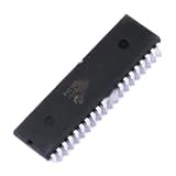
- 1 Pcs Microcontroller Chip Fit For MCU/MPU/SOC PIC18F45K50-I/P PDIP-40
These configuration settings are not ordinary run-time peripheral registers. XC8 encodes #pragma config declarations into the programming image; a programmer then writes those settings to the device. By contrast, OSCCON is a run-time control register. Microchip describes the #pragma config syntax and how XC8 handles configuration settings.
| Setting or field | Role | Where to verify it |
|---|---|---|
FOSC<3:0> |
Selects the primary oscillator mode and related pin behavior. | PIC18F45K50 data sheet and device-specific configuration-bit choices. |
OSCCON.IRCF<2:0> |
Selects an internal HFINTOSC frequency setting. | PIC18F45K50 oscillator-control register description. |
CFGPLLEN, PLLSEL, PLLEN, SPLLMULT |
Control or select PLL behavior according to the device’s configuration and clocking paths. | PIC18F45K50 PLL truth table and register descriptions. |
What INTOSCIO means
#pragma config FOSC = INTOSCIO selects INTOSC as the primary oscillator source and configures the oscillator-related pin for I/O, as defined for the PIC18F45K50. It does not mean “run at the highest internal frequency.” The related INTOSCCLKO mode selects the internal oscillator while retaining a clock-output function on the relevant pin. Check your schematic and pin use before choosing between them.
Rank #2

- 1 Pcs Microcontroller Chip Fit For MCU/MPU/SOC PIC18F45K50-I/PT TQFP-44 Fit For 10x10
The data sheet shows the internal-oscillator primary modes in the FOSC<3:0> truth table with the pattern 100x. Here, FOSC is a multi-bit field and the named XC8 option represents a device-specific encoding. The x indicates that the bit depends on which related mode is selected; it is not a wildcard value to copy into source code. Do not assume this pattern or these symbolic names apply to another PIC.
Choose the internal oscillator rate with IRCF
For the PIC18F45K50, the documented HFINTOSC selections include these IRCF<2:0> settings:
Rank #3

- DIP-40 MCU 8-bit Microcontrollers 32KB 1536 RAM 36I/O
IRCF<2:0> |
HFINTOSC setting |
|---|---|
111 |
16 MHz |
110 |
8 MHz |
101 |
4 MHz |
100 |
2 MHz |
011 |
1 MHz |
010 |
500 kHz |
001 |
250 kHz |
000 |
Depends on the associated oscillator-control state; consult the data sheet. |
For example, this shows the division of responsibilities in XC8:
#include <xc.h>

#pragma config FOSC = INTOSCIO

static void clock_init(void)
{
    OSCCONbits.IRCF = 0b111;  // Example: select the documented 16 MHz HFINTOSC setting
}
The IRCF assignment is an example for this device, not a complete clock-tree setup for every application. Consult the data sheet for any additional OSCCON controls and the resulting system-clock behavior. Keep the clock quantities distinct: oscillator frequency, selected system or primary clock, PLL output, peripheral clock, and instruction-cycle rate are not interchangeable labels. A 16 MHz HFINTOSC selection does not establish by itself that every clock domain or instruction timing is 16 MHz.
Rank #4

- Relays
- 5PCS/LOT PIC18F45K20-I/PT、PIC18F45K22-I/PT、PIC18F45K50-I/PT、PIC18F45K80-I/PT、LQFP44 Microcontroller chip
How the PLL controls fit in
CFGPLLEN, PLLSEL, PLLEN, and SPLLMULT concern PLL configuration, selection, enable behavior, or multiplier behavior. They do not replace FOSC or IRCF. The exact relationship depends on the selected clock source and the PIC18F45K50’s documented PLL path; use its truth table rather than a generic PIC example.
Quick wins for a faster PC:
Repair Windows errors before they cause bigger problemsFix Now →Fix the driver behind crashes, sound loss and screen glitchesFind Drivers →Clear out junk files and repair common Windows errorsFree Scan →The data sheet specifies that 3× PLL operation requires a 16 MHz input, while 4× PLL operation requires an 8–12 MHz input. Those are input requirements for the documented PLL modes, not universal output-frequency promises. Confirm that your chosen source and control-bit combination is valid before enabling a PLL.
Best Value

- 1 Pcs Microcontroller Chip Fit For MCU/MPU/SOC PIC18F45K50-I/MV UQFN-40 Fit For 5x5
Generate and verify the configuration in MPLAB X
- Confirm the project device. Check that the selected device is exactly
PIC18F45K50, not a similar PIC18 or PIC18LF part. - Open the Configuration Bits view. Select the required oscillator mode for the project device and use the generated configuration source as the starting point. MPLAB X labels and menu placement can differ between releases; Microchip documents its Configuration Bits view and generated source examples.
- Review the generated declarations. A typical declaration for the internal-oscillator I/O mode is
#pragma config FOSC = INTOSCIO. Keep the other generated settings appropriate to your project; this one line only addressesFOSC. - Set the run-time frequency. Configure the applicable
OSCCONfields, includingIRCFwhen selecting an HFINTOSC rate. Check the PIC18F45K50 register description for associated controls. - Validate any PLL combination. Use the device’s PLL truth table and specified input ranges. Do not copy settings from another device’s header or sample project.
- Check the effective clock. Use debugger register inspection, a timer calculation based on the documented clock domain, or a GPIO test signal measured with an oscilloscope or logic analyzer. A clock-output option can occupy a pin otherwise available for I/O. A UART that appears to work is not proof of the exact clock rate.
For typical XC8 projects, symbolic declarations are safer than manually packing configuration bits into hexadecimal values. Raw configuration words require checking the register address, bit polarity, reserved-bit requirements, device revision, and programmer behavior. Microchip also warns that configuration-bit options vary by device.
Troubleshoot an unexpected clock
- UART baud rate or timer timing is wrong: Check the actual oscillator selection,
IRCF, PLL path, and the clock domain used by the peripheral or timing calculation. Do not infer instruction-cycle frequency from the HFINTOSC setting alone. - The oscillator pin is not available as expected: Recheck whether the selected mode is
INTOSCIOor a clock-output mode, then compare the pin function with the schematic. - The PLL does not produce the expected clock: Verify the source frequency against the applicable 3× or 4× input requirement and check the complete truth-table combination for the selected source.
- The configuration view, header, or result seems inconsistent: Confirm the project device and XC8 device header, clean and rebuild, inspect the generated programming image or configuration view, and compare it with the data sheet’s configuration-register table.
Use the compiler’s documented #pragma config form for the selected device rather than mixing in older __CONFIG() syntax unless the applicable compiler and device documentation specifically calls for it.
Quick Recap
Quick selection checklist
- Confirm the exact PIC18F part number.
- Choose
FOSCfor the primary source and pin behavior. - Choose the internal HFINTOSC rate using the PIC18F45K50’s documented
OSCCONcontrols. - Configure PLL controls only for a documented source and input-frequency range.
- Verify the resulting clock in the intended clock domain and, where timing matters, in hardware.
Product prices and availability are accurate as of the date/time indicated and are subject to change. Any price and availability information displayed on Amazon at the time of purchase will apply.
The Tool Desk
Outbyte Driver Updater FREEFix the driver behind crashes, sound loss and screen glitchesFind Drivers →Outbyte PC Repair FREEClear out junk files and repair common Windows errorsFree Scan →
