Windows Errors? Fix Them Before They Spread
Repair common Windows errors and clear accumulated junk for a smoother, more stable PC - no reinstall needed.Free scan · no reinstallCrashes, No Sound, or Screen Glitches?
Random freezes, missing sound and display glitches usually trace back to one bad driver. Find and replace yours safely.Free scan · under a minuteSome links on this page are affiliate links: if you buy through them we may earn a commission, at no extra cost to you.
No. Many 555 timers share the same basic function and standard 8-pin layout, but that does not make every “555” an electrical drop-in replacement. If a board has an NE555N, the safest first choice is usually a reputable bipolar NE555 or LM555 in the same package, with ratings that suit the board. A CMOS part such as a TLC555 or LMC555 may work, but check the circuit before substituting it.
What “555” tells you—and what it doesn’t
“555” describes a widely used timer function, not one exact set of electrical specifications. Common bipolar parts include the NE555, LM555, SA555 and SE555. TLC555, LMC555 and ICM7555 are CMOS or low-power variants. They can share the familiar pin functions while differing in supply current, input behavior, output drive and operating limits.
On a standard single 8-pin 555, the usual pin functions are: pin 1 ground, pin 2 trigger, pin 3 output, pin 4 reset, pin 5 control voltage, pin 6 threshold, pin 7 discharge and pin 8 supply. TI’s LMC555 datasheet documents this assignment and identifies its PDIP, SOIC and VSSOP versions as pin-for-pin compatible with NE555, SE555 and LM555 families. Pin compatibility is useful, but it does not establish electrical equivalence or physical fit across packages.
Recommended Free Tools
Also distinguish a single 555 from a dual timer: an NE556 or LM556 contains two timer sections and typically has 14 pins, so it is not a direct replacement for a single 8-pin 555.
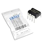
#1 Best Overall

- ALLECIN NE555 NE555P Timer - commonly used electronic components.
- Voltage: 4.5V-18V ; Current:10mA.
- Features & Advantages: Precise timekeeping accuracy & High-quality materials & Good temperature stability & Wide delay range.
- Widely Application: NE555 NE555P Timer is widely used in various applications.
- Humanized packaging for easy storage and use. # Printed markings for easy identification.
What does the “N” in NE555N mean?
The suffix is specific to the manufacturer’s ordering system. For many NE555 parts, “N” indicates a through-hole DIP-style package, but suffix letters can also identify package, temperature grade, qualification, lead finish or shipping format in other product lines. Do not use a universal suffix decoder: check the datasheet for the maker and the complete marking on your IC.
Photograph the chip before removing it. Record the manufacturer logo, every letter and number, package, date or lot code, and the notch or pin-1 dot. “NE555N” is more informative than “555,” but the full marking and the circuit still matter.
Rank #2

- Our pack includes 25 premium NE555 integrated circuits, designed for astable and monostable operation. These precision timers deliver consistent performance across microsecond to hour timing ranges, ideal for a vast array of electronic applications.
- Features adjustable duty cycle and TTL-compatible outputs capable of sinking or sourcing up to 200mA. Perfect for building pulse generators, oscillators, timers, alarms, LED flashers, and countless hobbyist and professional circuits.
- Each NE555 chip comes in an 8-pin dual in-line (DIP-8) package, compatible with breadboards, perfboards, and standard PCB sockets for easy prototyping and installation.
- Reliably operates from 4.5V to 15V DC, ensuring stable performance with common power supply configurations for both hobbyist and industrial electronic designs.
- Economical bulk pack of 25 pieces, perfect for electronic hobbyists, students, makers, and professionals. Stock up for multiple projects, repairs, and classroom experiments with high-quality, dependable components.
Bipolar and CMOS 555s: the practical difference
| Characteristic | Bipolar NE555/LM555 family | CMOS TLC555/LMC555/ICM7555 family |
|---|---|---|
| Typical design emphasis | Conventional timer behavior and legacy compatibility | Low power and high input impedance |
| Supply current | Generally higher, with more noticeable switching-current spikes | Generally lower; exact values depend on the device |
| Inputs and timing network | Input currents can matter with very large timing resistors | High input impedance can suit larger timing resistors and smaller capacitors |
| Output | Often able to sink substantial current, but not rail-to-rail high | Output voltage and source/sink capability vary by model |
| Supply and frequency limits | Check the selected part’s datasheet | Also model-specific; low-power or high-frequency claims are not universal |
These are family-level tendencies, not guarantees. Check the datasheet for the exact replacement. TI describes the TLC555 as a CMOS timer with a 2–15 V supply range and a 2.1 MHz rating, and the LMC555 as a low-power CMOS device capable of operation down to 1.5 V. Those specifications do not mean either device will behave exactly like an NE555 on every board.
Free tools Windows power users keep installed
One-click scans. No signup required.
A CMOS timer may fail to drive a load that the original bipolar device handled, or it may present a different output voltage to the next stage. Conversely, its low current and high input impedance can be helpful in a low-power design or with a high-resistance timing network. TI calls the TLC555 functionally interchangeable with the NE555 and gives it the same pinout; treat that as a useful starting point, not a blanket promise for an undocumented repair.
Rank #3
- Voltage: 4.5V-18V ; Current:10mA.
- Compact Powerhouse,Sleek, space-saving design fits seamlessly into tight devices—ideal for compact gadgets, DIY projects, or portable tech without compromising performance.
- Versatile Performance,Delivers reliable results across everyday tasks—whether amplifying signals, driving basic functions, or powering small circuits—making it a go-to for makers, hobbyists, and pros.
- Built to Endure,Resilient to daily wear, temperature shifts, and minor electrical fluctuations—engineered to keep your devices running smoothly, project after project.
- Effortless to Use,Standard pinout and user-friendly design work with most tools and boards—simplifies soldering, prototyping, and integration for beginners and experts alike.
Choosing a replacement for an NE555N
For an unknown board, start with another bipolar single 555 in the matching physical package. A bipolar NE555 or LM555 is often the conservative choice for an NE555 circuit, provided the specific device meets or exceeds the requirements below. “Often” is not “always”: check the original manufacturer’s datasheet and the board.
- Function and pinout: Confirm that it is a single timer with the same pin functions.
- Package: Match the through-hole DIP or surface-mount footprint, width, pin spacing and pin-1 orientation. A DIP and SOIC may share pin functions but cannot simply be swapped on the same footprint.
- Supply voltage: The part’s recommended operating range must cover the board’s actual supply. Do not rely on a family name or on absolute-maximum ratings as normal operating limits.
- Output load: Check what pin 3 drives and compare the load current and required high/low voltages with the datasheet. A relay, lamp, transistor base, optocoupler LED or charge-pump stage can impose different demands from a logic input.
- Timing and input conditions: Compare trigger, threshold, reset and control-voltage conditions, as well as timing resistance, capacitance and frequency.
- Temperature and qualification: If the equipment operates outside ordinary room conditions or has safety or reliability requirements, match the necessary grade and approvals.
Consider a TLC555, LMC555 or ICM7555 only after checking the circuit’s supply, output load, timing components, frequency and startup behavior. Do not assume that “CMOS” means universally better or that pin-for-pin means drop-in.
Rank #4
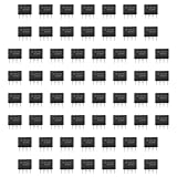
- Our pack includes 60 premium NE555 integrated circuits, designed for astable and monostable operation. These precision timers deliver consistent performance across microsecond to hour timing ranges, ideal for a vast array of electronic applications.
- Features adjustable duty cycle and TTL-compatible outputs capable of sinking or sourcing up to 200mA. Perfect for building pulse generators, oscillators, timers, alarms, LED flashers, and countless hobbyist and professional circuits.
- Each NE555 chip comes in an 8-pin dual in-line (DIP-8) package, compatible with breadboards, perfboards, and standard PCB sockets for easy prototyping and installation.
- Reliably operates from 4.5V to 15V DC, ensuring stable performance with common power supply configurations for both hobbyist and industrial electronic designs.
- Economical bulk pack of 60 pieces, perfect for electronic hobbyists, students, makers, and professionals. Stock up for multiple projects, repairs, and classroom experiments with high-quality, dependable components.
Diagnose the board before replacing the IC
A failed timer is only one possible cause of a dead or erratic board. A dried-out or leaky capacitor, drifted timing resistor, cracked solder joint, oxidized socket, bad regulator, damaged transistor, broken trace, shorted load or missing ground can produce similar symptoms. A replacement IC will not fix those faults, and a faulty socket or supply can damage the new part.
- Document the board. Photograph both sides, IC orientation, connectors, jumpers and component markings before disturbing anything. Identify the board’s purpose if possible.
- Check power safely. With power off, check for an obvious short between supply and ground. Then, where appropriate, use a current-limited supply and measure the voltage directly at pin 8 relative to pin 1. Check for abnormal current, heating, regulator problems or excessive ripple. Do not assume the board voltage from the IC marking.
- Inspect the socket and connections. Look for bent or recessed pins, loose or oxidized contacts, cracked solder and damaged traces. Check continuity from the socket contacts to nearby components. Verify correct IC orientation before powering the board.
- Check reset and control pins. Pin 4 reset is active-low; when unused it is normally tied to the positive supply. A reset line held low can keep the timer inactive. Inspect pin 5 control voltage and check whether pins 2 and 6 receive plausible signals. Standard 555 operation uses trigger and threshold references near one-third and two-thirds of the supply; reset overrides the timing inputs. See the TLC555 documentation and LMC555 datasheet.
- Inspect the timing network. Check the capacitor and resistors connected to pins 2, 6 and 7. Look for leakage, changed values, incorrect polarity or a capacitor held discharged. For a typical monostable circuit, pulse width is approximately
t ≈ 1.1RC. For a common astable arrangement, period is approximatelyT ≈ 0.693(RA + 2RB)C. These are approximations, not a substitute for checking component tolerance, leakage and operating conditions. - Use an oscilloscope if the fault involves pulses. A meter may average away a short pulse or fail to reveal an oscillator that never starts. Check supply and reset first, then inspect the timing-capacitor waveform, pin 7 discharge behavior and pin 3 output. In a functioning oscillator, the capacitor typically cycles between levels near one-third and two-thirds of the supply, while pin 3 produces a corresponding rectangular waveform. Connect scope grounds cautiously: a board may not be isolated from mains or another hazardous source.
Only replace the timer when the evidence points to it. If it is confirmed bad, install the chosen replacement with correct orientation, use antistatic handling, power up through current limiting and verify the output before reconnecting an external load.
Best Value

- Model: NE555
- Voltage: 4.5V-18V / Current: 10~15 mA / Output current (maximum): 225 mA / Rise/fall time: 100 ns
- 10 x NE555 NE555P NE555N timer ic
- 10 x 8 Pin DIP Socket
- Package: Total 20 Pcs
Quick substitution guide
| Original part or situation | Starting point | Check before fitting |
|---|---|---|
| NE555N in an 8-pin DIP footprint | Bipolar NE555 or LM555 in matching DIP | Supply, temperature and output-load ratings |
| NE555 or LM555 in SOIC | Bipolar single 555 in the same SOIC footprint | Package outline, pin 1 and electrical limits |
| NE555N replaced by TLC555 or LMC555 | Possible conditional substitution | Output drive and levels, supply, timing, startup and frequency |
| NE556 or LM556 | Another dual timer | It is not a single 8-pin 555 replacement |
| Unknown “555” marking | Identify the complete part first | Technology, package and datasheet—not just pin count |
For the basic pin functions and model-specific electrical limits, consult the manufacturer’s datasheet, such as TI’s NE555, TLC555 and LMC555 pages. If the part is obsolete in one package, that does not prove every 555 is unavailable—or that any available substitute is compatible. For a safety-critical or mains-connected board, do not substitute from a generic equivalence list; account for the original design, isolation and qualification requirements.
Quick Recap
Product prices and availability are accurate as of the date/time indicated and are subject to change. Any price and availability information displayed on Amazon at the time of purchase will apply.

