The 555 is a general-purpose timing and waveform-generation IC. With a few external resistors and capacitors, it can make a one-shot pulse, free-running oscillator, latch, Schmitt trigger, LED flasher, or control signal. Its timing is practical rather than precision-grade: resistor and capacitor tolerance, leakage, temperature, supply voltage, and the exact 555 variant all affect the result.
This guide explains the internal blocks, eight-pin interface, operating modes, bipolar versus CMOS versions, a safe first build, troubleshooting, and when another IC is the better choice.
What is a 555 timer?
“Timer” describes its original purpose, but the device is more versatile than a delay generator. External timing components determine how long its internal latch stays set or reset, allowing the 555 to produce pulses, oscillations, hysteresis, frequency division, pulse-width control, and simple waveform-generation functions.
The classic bipolar NE555 remains widely available. CMOS families such as the TLC555 use much less supply current and usually have lower input leakage, but their voltage limits, output behavior, timing limits, and pin specifications are not identical. Always identify the exact part number before designing around it.
Free tools Windows power users keep installed
One-click scans. No signup required.
#1 Best Overall

- Model: NE555
- Voltage: 4.5V-18V
- Current: 10~15 mA
- Output current (maximum): 225 mA
- Rise/fall time: 100 ns
The introductory laboratory sequence at All About Circuits continues with Schmitt-trigger, oscillator, monostable, LED-flasher, voltage-doubler, and transistor-drive experiments.
Inside the 555
A simplified block diagram is enough to understand most circuits. The internal divider creates nominal reference levels near one-third and two-thirds of the supply voltage. Two comparators watch external pins, an SR latch stores the state, a discharge transistor controls the timing capacitor, and an output driver presents the result at pin 3.
- Three-resistor divider: establishes nominal 1/3VCC and 2/3VCC references.
- Trigger comparator: responds when TRIGGER falls below the lower reference and sets the latch.
- Threshold comparator: responds when THRESHOLD rises above the upper reference and resets the latch.
- SR latch: remembers which comparator event occurred last.
- Discharge transistor: pulls the discharge node toward ground during the discharge interval.
- Output driver: drives pin 3 high or low, within the selected device’s current and voltage limits.
- RESET: asynchronously forces the output into its reset state when asserted.
- CONTROL VOLTAGE: shifts the comparator references when externally driven.
The ratios are more important than exact resistor values. Real thresholds are nominal, not guaranteed mathematical fractions; consult the chosen manufacturer’s data sheet for limits and conditions. See the TI NE555 data sheet or TI TLC555 data sheet.
555 timer pinout
For a standard single timer in an eight-pin DIP, hold the package with its notch or dot identifying pin 1. Pin numbering proceeds down one side and back up the other.
| Pin | Name | Function |
|---|---|---|
| 1 | GND | Negative supply or ground |
| 2 | TRIGGER | Sets the latch when below the lower threshold |
| 3 | OUTPUT | Timing or logic output |
| 4 | RESET | Active-low reset; hold high when unused |
| 5 | CONTROL VOLTAGE | Adjusts comparator reference levels |
| 6 | THRESHOLD | Resets the latch above the upper threshold |
| 7 | DISCHARGE | Open-collector-like internal transistor node for the timing capacitor |
| 8 | VCC | Positive supply |
- Do not mirror the pinout when transferring the IC to a breadboard.
- Do not leave RESET floating; tie it to the appropriate inactive level when unused.
- A small capacitor from CONTROL VOLTAGE (pin 5) to ground is commonly recommended when the pin is not being modulated.
- Pin 7 is a discharge node, not a normal push-pull output.
- Pin 3 should not directly power a motor, relay, solenoid, lamp, or high-current LED strip. Use a transistor or MOSFET stage and suitable suppression.
How trigger and threshold work
In the usual configuration, a falling trigger voltage below approximately 1/3VCC sets the latch. A rising threshold voltage above approximately 2/3VCC resets it. The control-voltage pin can move both reference levels, so these values are nominal rather than universal guarantees.
Rank #2

- Our pack includes 25 premium NE555 integrated circuits, designed for astable and monostable operation. These precision timers deliver consistent performance across microsecond to hour timing ranges, ideal for a vast array of electronic applications.
- Features adjustable duty cycle and TTL-compatible outputs capable of sinking or sourcing up to 200mA. Perfect for building pulse generators, oscillators, timers, alarms, LED flashers, and countless hobbyist and professional circuits.
- Each NE555 chip comes in an 8-pin dual in-line (DIP-8) package, compatible with breadboards, perfboards, and standard PCB sockets for easy prototyping and installation.
- Reliably operates from 4.5V to 15V DC, ensuring stable performance with common power supply configurations for both hobbyist and industrial electronic designs.
- Economical bulk pack of 25 pieces, perfect for electronic hobbyists, students, makers, and professionals. Stock up for multiple projects, repairs, and classroom experiments with high-quality, dependable components.
This separation creates hysteresis when the same changing voltage is connected to the timing network. The 555 Schmitt-trigger experiment demonstrates different switching points for rising and falling input, which helps clean up slow or noisy signals.
Main operating modes
Monostable: one-shot pulse
A monostable has one stable state. A trigger briefly starts the timing interval, then the output returns automatically. It is useful for push-button delays, debouncing, and fixed-width LED or buzzer pulses.
The idealized pulse-width relationship is t ≈ 1.1RC. Component tolerance, capacitor leakage, trigger shape, supply conditions, and device variation determine the actual result.
Astable: free-running oscillator
An astable continuously charges and discharges its timing capacitor. In the conventional two-resistor circuit:
tHIGH ≈ 0.693(RA + RB)C
tLOW ≈ 0.693RBC
T ≈ 0.693(RA + 2RB)C
f ≈ 1.44/[(RA + 2RB)C]
Rank #3

- Timing From Microseconds to Hours
- Astable or Monostable Operation
- Adjustable Duty Cycle
- TTL-Compatible Output Can Sink or Source up to 200 mA
The standard arrangement does not normally produce a 50% duty cycle because charging and discharging use different resistance paths. A diode-assisted or alternative arrangement is needed when independent duty-cycle adjustment matters.
Bistable: latch
With external set and reset signals, the 555 can retain an on/off state. This suits toggle controls and simple event-state storage, although a dedicated logic latch may be smaller or lower power.
The Tool Desk
Outbyte PC Repair FREEClear out junk files and repair common Windows errorsFree Scan →Outbyte Driver Updater FREEScan for outdated or missing drivers - takes under a minuteDriver Scan →Schmitt trigger
Using the comparator thresholds and feedback, the 555 turns a slowly changing or noisy voltage into a cleaner two-state signal with hysteresis.
Bipolar NE555 versus CMOS 555
| Consideration | Bipolar NE555-type | CMOS TLC555/TS555-type |
|---|---|---|
| Supply current | Usually higher | Much lower |
| Battery operation | Less efficient | Usually preferable |
| Input leakage | Generally higher | Usually much lower |
| Low-voltage use | Often more restricted | Often supports lower supplies |
| Output behavior | Traditional bipolar stage; current is device-specific | Device-specific; do not assume NE555 drive capability |
| Replacement status | Often pin-compatible, but never assume electrical equivalence | |
Compare minimum and maximum supply voltage, source and sink current, input thresholds, discharge behavior, maximum frequency, temperature range, and package before substituting. Official references include the TI NE555 and TI TLC555 product pages.
Dual and quad timer packages
A 556 contains two independent timer sections in one larger package, useful when two timing functions share a board and supply. Other multi-timer parts may contain more channels, but their pinouts and electrical characteristics differ from a single eight-pin 555. Use the exact package data sheet rather than assuming four interchangeable standard timers.
Rank #4

- ALLECIN NE555 NE555P Timer - commonly used electronic components.
- Voltage: 4.5V-18V ; Current:10mA.
- Features & Advantages: Precise timekeeping accuracy & High-quality materials & Good temperature stability & Wide delay range.
- Widely Application: NE555 NE555P Timer is widely used in various applications.
- Humanized packaging for easy storage and use. # Printed markings for easy identification.
First build: a safe LED flasher
- Identify the exact 555 part and confirm its permitted supply range.
- Use a regulated low-voltage supply within that range; connect pin 1 to ground and pin 8 to the supply.
- Hold pin 4 high if reset is unused, and fit the recommended bypass capacitor from pin 5 to ground.
- Place a supply-decoupling capacitor close to the IC’s supply pins.
- Wire an astable network with the timing capacitor at the threshold/discharge node and calculate the expected period from the equations above.
- Drive an LED through a current-limiting resistor from pin 3. Never connect an LED directly.
- Measure the timing-capacitor voltage with a multimeter or oscilloscope. It should ramp between approximate comparator thresholds.
- Change one resistor or capacitor at a time and compare measured frequency and duty cycle with the calculated values.
Use ceramic capacitors for supply bypassing. Electrolytic timing capacitors are convenient at long delays but have greater leakage and tolerance; check polarity and expect larger errors. Keep breadboard wires short when the output switches quickly or drives a noisy load.
Do these 3 things before closing this tab:
1Repair Windows errors before they cause bigger problems2Scan for outdated or missing drivers - takes under a minute3Clear out junk files and repair common Windows errorsProjects to build next
- Schmitt trigger: observe hysteresis with a potentiometer and LEDs.
- Astable oscillator: vary R or C and verify frequency against the timing equation.
- Monostable multivibrator: make a push-button-controlled pulse.
- LED flashers: compare timing networks and duty cycles.
- Voltage doubler: explore charge-pump behavior, while observing current and ripple limits.
- Transistor-driven output: buffer an LED bank or inductive load with a transistor or MOSFET, adding a flyback diode where required.
The chapter’s project index is listed in the All About Circuits Electronics Textbook reference.
Independent reader supportYour contribution helps us test, update, and keep practical guides available for everyone.Troubleshooting checklist
No oscillation or output
- Check notch orientation, pin numbering, ground, and supply connections.
- Verify that RESET is not low or unintentionally floating.
- Recheck pins 2, 6, and 7 against the intended schematic.
- Inspect capacitor polarity and confirm resistor/capacitor units.
- Confirm the CMOS part is within its voltage range.
Frequency is wrong
- Account for resistor and capacitor tolerance and electrolytic leakage.
- Check nF versus µF markings and ensure the formula matches the actual wiring.
- Reduce measurement loading on the timing node; an oscilloscope probe can affect high-resistance networks.
- Consider supply voltage, temperature, and operation outside the device’s recommended timing range.
Unstable output or damaged/dim LED
- Add close supply bypassing and shorten long breadboard wires.
- Keep motors and other noisy loads off the output pin unless buffered.
- Use a current-limiting LED resistor and observe that source and sink capability may differ.
- Protect inductive loads with the appropriate transistor and flyback suppression.
One 555 works while another does not
Different minimum supplies, thresholds, leakage, output voltage, discharge behavior, and current limits can make substitutions fail. Compare both data sheets rather than relying on the shared “555” label.
When a 555 is the wrong tool
- Choose a microcontroller for programmable timing, multiple states, communications, or firmware-adjustable behavior.
- Choose a dedicated oscillator or clock IC for tighter frequency accuracy, efficiency, or high-frequency operation.
- Choose a comparator or Schmitt-trigger gate when the task is mainly threshold detection or signal cleanup.
- Choose a supervisor, PWM controller, or power-management IC when protection and regulated power behavior matter.
- Choose a precision reference or timer when component and device tolerances cannot meet the timing requirement.
A 555 is excellent for transparent, inexpensive experiments and simple control circuits. It is not automatically suitable for safety-critical, precision, automotive, or production equipment.
Frequently Asked Questions
Can a 555 run from 3.3 V?
Some CMOS 555 devices support 3.3-V operation, while many bipolar NE555 parts do not meet their specifications there. Check the exact data sheet.
Best Value
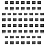
- Our pack includes 60 premium NE555 integrated circuits, designed for astable and monostable operation. These precision timers deliver consistent performance across microsecond to hour timing ranges, ideal for a vast array of electronic applications.
- Features adjustable duty cycle and TTL-compatible outputs capable of sinking or sourcing up to 200mA. Perfect for building pulse generators, oscillators, timers, alarms, LED flashers, and countless hobbyist and professional circuits.
- Each NE555 chip comes in an 8-pin dual in-line (DIP-8) package, compatible with breadboards, perfboards, and standard PCB sockets for easy prototyping and installation.
- Reliably operates from 4.5V to 15V DC, ensuring stable performance with common power supply configurations for both hobbyist and industrial electronic designs.
- Economical bulk pack of 60 pieces, perfect for electronic hobbyists, students, makers, and professionals. Stock up for multiple projects, repairs, and classroom experiments with high-quality, dependable components.
Can a 555 drive a relay?
Use a transistor or MOSFET driver, a flyback diode, and a suitable supply. Do not connect a relay coil directly to pin 3.
Why is the astable duty cycle not 50%?
In the standard circuit, the capacitor charges through R_A + R_B but discharges through R_B, so the high and low intervals differ.
How accurate is a 555 timer?
Timing is approximately set by the external R and C values. Tolerance, leakage, temperature, supply variation, and device thresholds determine real accuracy.
What capacitor belongs on pin 5?
A small bypass capacitor to ground is commonly recommended when CONTROL VOLTAGE is unused; follow the selected manufacturer’s application circuit.
What’s actually slowing this PC down?
Pick the symptom - the matching free tool is one click away.
Quick Recap
Product prices and availability are accurate as of the date/time indicated and are subject to change. Any price and availability information displayed on Amazon at the time of purchase will apply.

